Why Emulsified Oil Wastewater Is the Hardest Stream to Treat
Emulsified oil droplets below 20 µm carry a surface charge, are sheathed by surfactant molecules, and resist gravitational separation for weeks — which is why a metalworking shop can run a skim oiler for years and still fail a discharge test on total oil. The industry groups oily wastewater into three droplet-size classes that map directly to the unit operation you should pick: free oil at >150 µm separates in minutes under gravity, dispersed oil at 20–150 µm separates over hours in an API separator, and emulsified oil at <20 µm — frequently <5 µm — is stabilized by surfactants and will not separate without chemistry or a membrane (per the LiqTech O-WaR project review, 2024-09). Emulsified oil is the dominant fraction in metalworking coolant wastewater, vegetable-oil processing condensate, refinery desalter effluent, and oilfield produced water. Typical influent loads run 500–10,000 mg/L total oil, and 60–90% of that load sits in the emulsified fraction in coolant and produced-water streams (HydropureWater field data, 2026). Three mechanisms keep the droplets stable: surfactant adsorption at the oil–water interface, electrostatic repulsion from the negatively charged droplet surface (zeta potential typically −30 to −50 mV), and mechanical shear from pumps and headers that re-disperses any droplet that begins to coalesce. If your stream is genuinely emulsified, gravity and skimming alone will not clear it, and the wrong coagulant can make it worse.
The Three-Tier Process Map Used in 2026
A 2026 best-practice train is organized in three tiers — Pretreatment → Primary separation → Polishing/Reuse — and every later technology plugs into one of those slots (per LiqTech O-WaR, 2024-09). Tier 1 (Pretreatment) handles equalization, pH trim to 6.5–8.0, coarse screening to 0.5–1.0 mm, and tramp-oil removal so chemistry in Tier 2 sees a consistent feed. Tier 2 (Primary separation) is where the emulsion is broken: chemical demulsification or coagulation–flocculation followed by dissolved air flotation, or direct membrane separation if the feed is already <100 mg/L oil. Tier 3 (Polishing/Reuse) deploys ultrafiltration, a silicon carbide ceramic membrane, nanofiltration, or reverse osmosis to hit the discharge or reuse spec; RO and NF are typically reserved for boiler-feed or high-pressure cooling-tower makeup where conductivity must drop below 50 µS/cm. The six conventional unit operations the O-WaR review lists — gravity separation, skimming, DAF, de-emulsification, coagulation, and flocculation — all live in Tiers 1 and 2; membranes are the Tier 3 workhorses. Skipping Tier 1 is the single most common reason a downstream membrane fouls inside 30 days.
Demulsification and Coagulation Chemistry: Breaking the Emulsion First
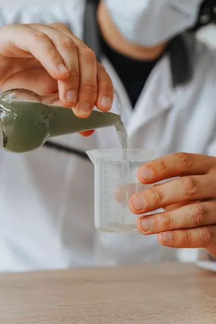
The whole train rises or falls on whether the emulsion is broken before it reaches the separator. The widely cited coagulation–flotation study on emulsified oil showed polyferric sulfate (PFS) dosed at 250–400 mg/L took a 3,000–5,000 mg/L emulsified feed to a stable 38–51 mg/L (≈15 ppm) effluent at 0.25 m³/h on a microbubble DAF (per ScienceDirect, 2018-04). PFS works because Fe³⁺ hydrolyzes into polynuclear cationic species that neutralize the negative zeta potential of surfactant-stabilized droplets, allowing coalescence. Cationic demulsifiers — quaternary polyamines, dicyandiamide-formaldehyde resins — suit surfactant-stabilized emulsions from metalworking and veg-oil plants; anionic demulsifiers (sulfonates, fatty-acid blends) fit oilfield produced water where the native surfactants are different. A 1–5 mg/L polyacrylamide (PAM) flocculant dose after the coagulant builds a dense, floatable floc with a positive settling (or floating) index. The break-point trap is real: under-dosing leaves the emulsion intact, while over-dosing re-stabilizes the droplets because excess PFS hydrolyzes into polynuclear hydroxy complexes that re-charge the surface — both ends of the curve produce high effluent oil (per the same ScienceDirect source). A defensible jar-test protocol runs 6 beakers at 50, 100, 200, 300, 400, 500 mg/L PFS, 1 min rapid mix at 200 rpm, 10 min slow mix at 30 rpm, then 5 min settling, with supernatant oil measured by an IR method equivalent to EPA 1664. Lock the dose from the jar test, then deliver it with an automatic coagulant and flocculant dosing skid sized to the actual peak flow.
Dissolved Air Flotation: The Workhorse for 1,000–5,000 mg/L Feeds
DAF is the right primary separator when the feed carries 1,000–5,000 mg/L emulsified oil and the discharge target sits around 10–30 ppm — that is, when a downstream membrane is not yet justified. Design around an air-to-solids (A/S) ratio of 0.02–0.06 (mass air / mass oil+SS), a recycle rate of 20–40% of forward flow, and a microbubble size of 10–50 µm, with the finer 20–30 µm fraction preferred for emulsified oil because the smaller bubble raises droplet–bubble collision probability (per the ScienceDirect coagulation–microbubble flotation study, 2018-04). Surface loading rate typically runs 5–20 m/h with hydraulic residence time of 15–30 min. On a 3,000–5,000 mg/L feed with PFS coagulation, a properly tuned DAF routinely hits 10–30 ppm effluent; pushing below 10 ppm from DAF alone usually requires a two-stage configuration with intermediate microbubble regeneration, common in metalworking plants running close-tolerance parts. Specify a dissolved air flotation system with a saturator holding 5–6 bar, a recycle pump sized to 30% of forward flow, and a scraper torque rated for the expected floated solids (typically 2–4% of feed volume). For sizing methodology on a related high-solids stream, the DAF system sizing for starch wastewater guide covers the same A/S and recycle-rate arithmetic in detail.
Ultrafiltration: Closed-Loop Emulsion Recovery
UF is the workhorse polishing step when the goal is to recover the emulsion for reuse, not just to clear the discharge. Polymeric UF in PVDF or PES at 0.01–0.1 µm pore size, or ceramic UF at similar ratings, runs at 50–150 L/m²·h under crossflow with a transmembrane pressure (TMP) of 0.5–2.0 bar — above ~2.5 bar the gel layer compacts and flux collapses. Up to 95% of the feed exits as reusable permeate, and the concentrate — about 5% of feed volume — can be incinerated or, if the plant runs a single oil/emulsifier package, recycled directly back to the process (per Applied Membranes UF case data, 2024-11). A documented 200 gal/day of recovered oil translates to roughly $500/day of avoided makeup and disposal cost in a single-source emulsion plant. The hard constraint: feed oil to UF should be below 50–100 mg/L, otherwise irreversible fouling sets in within hours — that is why DAF must precede UF rather than stand alone. For plants already considering a biological step downstream, a submerged MBR system can replace the UF stage when the reuse target is process rinse water rather than emulsion recovery.
Silicon Carbide Ceramic Membranes: The 2026 Standard for Tough Emulsions
When polymeric UF fouls too fast on highly emulsified feeds, the 2026 upgrade path is a silicon carbide ceramic membrane. SiC tolerates the full pH window (0–14), operating temperatures up to ~95°C, and aggressive cleaning chemistries (NaOH up to 5%, HCl up to 5%, oxidizers) that would destroy polymeric UF. Pore ratings down to 0.04 µm give sub-micron droplet rejection with no pore deformation under back-pressure. The O-WaR project's anti-fouling nano-particle coating keeps flux stable 3–5× longer than uncoated ceramics on highly emulsified oil feeds (per LiqTech O-WaR, 2024-09) — that is the engineering answer to the fouling barrier the same paper flagged as the #1 commercialization inhibitor. Permeate oil is typically <1 mg/L, suitable for cooling-tower makeup or as RO/NF feed. The trade-off is real: CAPEX runs 2–3× per m² of polymeric UF, but lifetime cost is lower on difficult feeds because cleaning cycles are shorter, chemical use is lower, and membrane life exceeds 10 years. For the design math, the silicon carbide membrane design guide covers the flux, TMP, and cleaning-recovery numbers in detail.
Process Selection Matrix: DAF vs UF vs SiC Membrane
The table below maps influent oil concentration and reuse target to the right unit operation, with the 2026 equipment CAPEX envelope. Numbers are order-of-magnitude export-pricing anchors for Chinese-supplier skids, intended for early budgeting only (HydropureWater field data, 2026).
| Unit operation | Influent oil (mg/L) | Effluent oil target | Best fit | Key design parameter | 2026 CAPEX anchor (USD per m³/d) |
|---|---|---|---|---|---|
| DAF alone | 500–5,000 | 10–30 ppm; no reuse | Discharge only, no water-reuse target | A/S 0.02–0.06; recycle 20–40%; bubble ≤30 µm | $800–$1,500 |
| DAF + polymeric UF | 500–5,000 | <5 ppm; partial reuse (rinse water) | Metalworking coolant recovery, single oil package | UF flux 50–150 L/m²·h; TMP 0.5–2.0 bar | $2,200–$3,800 |
| DAF + SiC ceramic membrane | 1,000–10,000 | <1 ppm; full reuse (cooling-tower makeup, RO feed) | Refinery desalter, produced water, tough emulsions | 0.04–0.1 µm SiC; TMP 0.5–3.0 bar; CIP 1–2×/week | $3,500–$6,000 |
| DAF + SiC + RO/NF polish | 1,000–10,000 | <0.1 ppm oil; conductivity <50 µS/cm | Boiler feed, high-pressure cooling-tower makeup | RO recovery 60–75%; NF for monovalent cut | $4,500–$8,000 |
OPEX trends the other way: DAF-only is the cheapest to install but offers no reuse credit; SiC-based trains cost more upfront but recover 90–95% of the water, drop chemical use, and reduce incineration volume, so the 5-year total cost of ownership usually favors SiC on feeds above 3,000 mg/L.
Designing a 2026 Treatment Train: A Worked Example
Take a 10 m³/h metalworking coolant wastewater plant with influent oil 4,000 mg/L, pH 8.5, COD ~6,000 mg/L, TSS 300 mg/L. The 2026 train sequences equalization → pH trim to 7.0 with sulfuric acid → PFS at 300 mg/L plus PAM at 2 mg/L → DAF at A/S 0.04 with 30% recycle → 0.05 µm SiC ceramic membrane → RO for 50% permeate reuse. Expected performance: DAF effluent ~20 ppm oil, SiC permeate <1 ppm, RO permeate conductivity <50 µS/cm (HydropureWater field data, 2026). Indicative equipment CAPEX for a 10 m³/h plant in 2026 sits around $25,000 for the DAF skid, $80,000 for the SiC skid, and $35,000 for the RO skid — order-of-magnitude only and sensitive to automation scope and material of construction. Floated sludge from the DAF runs roughly 3% solids and routes to a small plate and frame filter press for dewatering to 25–30% dry solids before disposal. The same pH-trim, DAF, and sludge-handling pattern shows up in the printing and dyeing wastewater treatment guide for analogous high-COD streams, which is useful for cross-checking the equalization volume and the flocculant dose.
Pilot Protocol: Four Tests to Run Before Full-Scale Design
De-risk the design with four low-cost tests on the actual wastewater before any purchase order goes out. Test 1 — Jar test: sweep PFS at 50, 100, 200, 300, 400, 500 mg/L, identify the optimum and confirm no re-stabilization at higher doses (per the ScienceDirect coagulation–flotation study, 2018-04). Test 2 — Bench DAF: a 2 L cylinder with a small saturator confirms the A/S ratio and the floated-solids concentration. Test 3 — Membrane coupon: a 0.05 µm SiC disc on a 30-day crossflow loop tracks flux decline and cleaning frequency, and validates the anti-fouling coating's recovery. Test 4 — Whole-train shake-down: a 24-hour continuous run on the candidate train measures oil (IR), COD, TSS, and energy on every stream. The output is a single design memo that locks the unit-operation sequence, doses, and design fluxes — that memo is what you defend in front of the plant manager, the EHS lead, and the CFO.
Frequently Asked Questions
What influent oil concentration requires a membrane instead of DAF alone? Above roughly 1,000 mg/L of emulsified (sub-20 µm) oil, DAF alone typically plateaus at 10–30 ppm, so any reuse or <10 ppm discharge target needs a downstream UF or SiC ceramic membrane (HydropureWater field data, 2026).
What is the standard PFS dose for emulsified oil wastewater? Polyferric sulfate at 250–400 mg/L is the documented window that takes a 3,000–5,000 mg/L emulsified feed to a stable ~15 ppm effluent after microbubble DAF, with sharp deterioration in performance both below and above that range (per ScienceDirect, 2018-04).
Why does DAF have to precede UF? Feed oil above 50–100 mg/L causes irreversible fouling of polymeric UF within hours; DAF brings the feed into that window first, so the membrane can run at 50–150 L/m²·h with TMP below 2.0 bar instead of collapsing under a compacted gel layer.
What is the 2026 CAPEX envelope for an emulsified oil treatment train? A DAF-only skid runs $800–$1,500 per m³/d of capacity; DAF plus polymeric UF runs $2,200–$3,800; DAF plus SiC ceramic membrane runs $3,500–$6,000; adding RO/NF polish pushes the upper end to $8,000 per m³/d (HydropureWater field data, 2026, order-of-magnitude only).
Why is silicon carbide displacing polymeric UF for emulsified oil in 2026? SiC tolerates pH 0–14, temperatures to ~95°C, and aggressive clean-in-place chemistries, and an anti-fouling nano-particle coating extends stable flux 3–5× over uncoated ceramics — directly addressing the membrane-fouling barrier the LiqTech O-WaR project identified as the main commercialization blocker (per LiqTech O-WaR, 2024-09).