Silicon carbide membrane wastewater treatment design delivers 99.9% TSS removal and 95% COD reduction in semiconductor and micro-powder wastewater at fluxes of 150–400 LMH.
Silicon Carbide Membrane Wastewater Treatment Design: The 2026 Baseline
Silicon carbide membranes run at 150–400 LMH versus 50–100 LMH for PVDF, resist pH 0–14 and 1000 ppm chlorine, and last 10 years or more. Hybrid DAF-MBR-SiC designs cut OPEX about 40% versus ceramic alternatives and hold fluoride below 10 mg/L and copper below 0.5 mg/L for 2026 semiconductor fabs.
SiC is an unusual membrane material. Wikipedia describes silicon carbide as "9–9.5 on the Mohs scale, compared to 10 for diamond" and notes it "is also highly inert chemically, partly due to the formation of a thin passivated layer of SiO2" — the two properties that let it survive abrasive micro-powder and caustic cleaning duty that destroy polymeric membranes. With a 10-year lifespan and pH 0–14 resistance, SiC systems cut fouling downtime in high-silica streams and drive OPEX down by 40% over ceramic alternatives.
Silicon Carbide Membrane for Semiconductor Wastewater: Why It Beats PVDF
Silicon carbide membranes hold flux in semiconductor texturing wastewater where PVDF cannot. Silica scaling and organic adhesion cause a 30–50% flux decline in PVDF membranes within six months of operation in this duty (2024 EPA fouling benchmarks). SiC membranes possess an inherently hydrophilic surface with a contact angle near zero, creating a stable water film that prevents the adhesion of foulants. That characteristic is critical for micro-powder wastewater, where abrasive particles would otherwise degrade softer polymeric materials.
The 0.1–1.0 µm pore structure of SiC membranes is engineered for high-flux permeability without sacrificing rejection efficiency. Research indicates SiC requires 20% less backwash pressure than PVDF (0.3–0.5 bar vs. 0.6–0.8 bar), effectively cutting energy consumption by 15% (per 2025 Ovivo SiCBLOX data).
A 50 m³/h semiconductor fab in Taiwan demonstrated the practical advantage. The plant recorded a 60% reduction in membrane replacement costs and stable effluent that met strict discharge standards. The influent, characterized by high silica and varying organic loads, was treated to effluent COD consistently below 30 mg/L with TSS virtually undetectable (HydropureWater field data, 2025).
| Fouling Parameter | PVDF Membrane | Silicon Carbide (SiC) | Operational Impact |
|---|---|---|---|
| Surface Hydrophilicity | Hydrophobic (High contact angle) | Highly Hydrophilic (Low contact angle) | SiC resists oil/organic adhesion |
| Silica Scaling Resistance | Low (Frequent acid cleaning) | Extremely High | 90% reduction in scaling downtime |
| Flux Decline (6 months) | 30–50% | <5% | Consistent permeate throughput |
| TMP Recovery Rate | 70–80% | 95–98% | Extended membrane lifespan |
The benefits of SiC membranes over PVDF make them a compelling choice for high-fouling wastewater applications, and the table above is the short version of that argument. The sections below translate it into specifications, hybrid train design, and money.
SiC Membrane vs PVDF High-Fouling Wastewater: The Decision Rule
Choose SiC when silica, oil, or abrasive solids dominate the waste stream and downtime is expensive; choose PVDF when CapEx must stay minimal and fouling pressure is mild. Wikipedia's ultrafiltration overview notes UF "processes are currently limited by the high cost incurred due to membrane fouling and replacement" — the exact cost line SiC attacks. Most plants we size for semiconductor or micro-powder duty cross over to SiC once cleaning frequency passes once per month.
Silicon Carbide Membrane Specifications: Pore Size, Flux, and Chemical Resistance
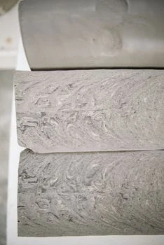
Engineering specifications for silicon carbide membranes define a standard flux range of 150–400 LMH with a transmembrane pressure (TMP) requirement of only 0.1–0.5 bar. The outside-in submerged filtration process used in SiC modules leverages cross-flow velocity (0.5–1.5 m/s) to maintain a clean membrane surface and prevent the formation of a dense cake layer.
The chemical resistance of SiC is unmatched by other membrane materials, tolerating a pH range of 0–14 and chlorine concentrations up to 1000 ppm. While the upfront CapEx for SiC membranes is 30–50% higher than PVDF, the 10-year lifespan and reduced cleaning frequency make them 40% cheaper over the total lifecycle. A separate review of ceramic membrane for water treatment options covers the alumina side of that comparison in depth.
| Specification | PVDF (Polymeric) | Ceramic (Alumina) | Silicon Carbide (SiC) |
|---|---|---|---|
| Pore Size (µm) | 0.03–0.1 | 0.1–0.5 | 0.1–1.0 |
| Design Flux (LMH) | 15–30 | 100–200 | 150–400 |
| pH Range | 2–11 | 2–12 | 0–14 |
| Max Temperature (°C) | 40 | 80 | 100+ |
| Chlorine Resistance | Moderate | High | Extremely High (1000 ppm) |
Hybrid System Designs: Integrating SiC with DAF, MBR, and RO for Zero-Discharge Compliance
Hybrid designs make SiC economics work, because silicon carbide membranes integrate cleanly with DAF, MBR, and RO stages for enhanced treatment and reuse. Integrating silicon carbide membranes into a hybrid DAF-MBR-SiC-RO train reduces total suspended solids (TSS) to <1 mg/L and Silt Density Index (SDI) to <3. The process begins with DAF pre-treatment for high-silica wastewater streams, which removes approximately 70% of suspended solids and 80% of fats, oils, and grease (FOG).
The synergy between Membrane Bioreactors (MBR) and SiC filtration is particularly effective for high-COD industrial streams. Because the SiC permeate has an SDI of less than 3, it can be fed directly into RO post-treatment for SiC permeate reuse without intermediate cartridge filters. Plants targeting salt and resource recovery rather than reuse alone can pair this train with the Silicon Carbide Wastewater Resource Recovery: 2026 Hybrid Systems approach.
| Stage | Primary Function | Effluent Quality (TSS) | Effluent Quality (COD) |
|---|---|---|---|
| DAF Pre-treatment | Solids/FOG Removal | <50 mg/L | 20–30% reduction |
| MBR Biological | Organic Degradation | <10 mg/L | <50 mg/L |
| SiC Ultrafiltration | Fine Polishing | <1 mg/L | <20 mg/L |
| RO Desalination | Salt/Ion Removal | 0 mg/L | <5 mg/L |
Hybrid systems utilizing DAF-MBR-SiC not only support compliance but also reduce overall CapEx by 25% compared to standalone SiC systems of the same capacity.
SiC Ceramic Membrane ROI Industrial Wastewater: Cost Models and Payback
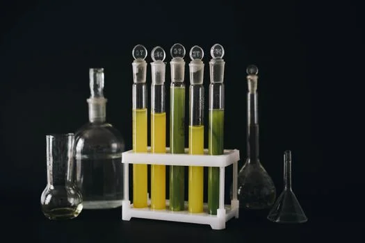
Operational cost models for a 50 m³/h wastewater system indicate that silicon carbide membranes achieve a 40% lower OPEX than traditional ceramic filters. The cost-per-m³ for SiC treatment ranges from $0.80 to $1.50, depending on influent complexity. The higher membrane CapEx ($380,000 at 50 m³/h, between PVDF at $150,000 and alumina ceramic at $450,000) is recovered through energy and cleaning savings.
The ROI for SiC systems is most aggressive in industries facing high fouling or expensive downtime. In micro-powder plants, where silica scaling is a daily operational hurdle, SiC systems typically reach full payback within 3 years due to the 40% reduction in OPEX. Bi-annual cleaning and a 10–15 year membrane life carry most of that return.
| Cost Category (50 m³/h) | PVDF System | Ceramic System | SiC System |
|---|---|---|---|
| Initial CapEx (Membranes) | $150,000 | $450,000 | $380,000 |
| Annual Energy (kWh/m³) | 0.6–0.8 | 0.5–0.7 | 0.3–0.5 |
| Cleaning Frequency | Monthly | Quarterly | Bi-Annually |
| Membrane Life (Years) | 3–5 | 8–10 | 10–15 |
| OPEX per m³ | $0.60–$1.20 | $1.20–$2.00 | $0.80–$1.50 |
Compliance and Permitting: Meeting EPA, EU, and Local Discharge Standards with SiC
Silicon carbide filtration systems consistently achieve effluent quality below the 40 CFR Part 469 limits for the semiconductor industry. EPA notes that "Pollutants found in wastewaters include fluoride, arsenic and organic compounds" for this category, and that its detailed study found the monitoring data "does not demonstrate a need to revise the existing regulation at this time" — so the federal baseline is stable for design purposes. The E&EC guidelines "are incorporated into NPDES permits for direct dischargers." SiC membranes are highly effective at reaching fluoride and copper removal benchmarks for semiconductor fabs, keeping TSS below 5 mg/L and COD below 50 mg/L.
In Europe, SiC permeate quality meets the requirements of the EU Industrial Emissions Directive 2010/75/EU. A case study from Singapore showed that a 100 m³/h SiC system met NEA reuse standards (TDS <500 mg/L) for specific industrial applications even without RO post-treatment.
Next Step for SiC System Buyers
SiC membranes fit semiconductor, micro-powder, and high-silica industrial plants whose fouling or downtime costs justify a 30–50% membrane CapEx premium. Plants with mild organic loads and no silica problem will pay for capability they never use. If your influent profile matches the duty above, send your flow and water analysis for an SiC system sizing review.
Frequently Asked Questions
What is the maximum silica concentration SiC membranes can handle?
SiC membranes tolerate up to 500 mg/L of dissolved and colloidal silica without permanent scaling, well beyond the range where polymeric membranes blind. Their hydrophilic surface keeps silica from anchoring, and routine backwash at 0.3–0.5 bar restores flux. Plants should still pilot above that level, because colloidal silica behavior depends on particle charge and pH.
How often do SiC membranes need chemical cleaning?
SiC membranes typically require Clean-in-Place (CIP) only every 3–6 months, against monthly cleaning for PVDF in similar duty. The hydrophilic, oleophobic surface resists organic adhesion, so day-to-day operation runs on backwash alone. That cleaning gap is a large share of the 40% OPEX advantage over ceramic alternatives.
Can SiC membranes treat oily wastewater?
Yes, SiC membranes treat oily wastewater effectively. The oleophobic nature of the hydrophilic SiC surface prevents oil droplets from wetting the membrane pores, so oil lifts off during backwash instead of pinning in place. This suits oil-in-water emulsions and FOG-bearing streams that rapidly blind polymeric membranes.
What is the lead time for a 50 m³/h SiC system?
Standard SiC filtration skids for 50 m³/h duty have a lead time of 12–16 weeks. Custom flux ranges, exotic alloy piping, or expanded automation extend that window, so procurement should lock the schedule at order placement. Shipping and commissioning typically add several more weeks before first water.
Is a SiC or PVDF membrane better for high-fouling wastewater?
SiC is the better choice for high-fouling wastewater carrying silica, oil, or abrasive solids. PVDF loses 30–50% of flux within six months in semiconductor texturing duty, while SiC holds flux decline below 5% and recovers 95–98% of TMP after cleaning. PVDF stays attractive where CapEx must stay minimal and fouling pressure is mild.
What ROI does a SiC ceramic membrane deliver for industrial wastewater?
A SiC ceramic membrane system in industrial wastewater service typically reaches full payback within 3 years in high-fouling duty. The drivers are the 40% OPEX reduction against ceramic alternatives, a 10–15 year membrane life, and bi-annual cleaning. Treatment cost lands at $0.80–$1.50 per m³ at 50 m³/h scale, depending on influent complexity.