Semiconductor wastewater treatment design with digital twins now anchors 2026 fab water strategy: hybrid DAF-RO-MBR trains at 500 m³/h achieve 95%+ water reuse while digital models cut chemical and energy OPEX 20–25%.
Semiconductor Wastewater Treatment Design with Digital Twins: the 2026 Baseline
A 500 m³/h semiconductor fab needs a three-stage DAF-RO-MBR train: DAF at 4–8 m/h removes 92–97% of TSS, RO recovers 85–95% of the water, and MBR polishes COD to ≤50 mg/L. Digital twins then trim OPEX 20–25% by optimizing dosing schedules and membrane cleaning cycles.
Fab water strategy now starts from the reuse loop, not the discharge permit. Advanced fabrication plants consume several million gallons of ultrapure water per day (Wikipedia), so every cubic meter reclaimed is a cubic meter not purchased, pretreated, and polished to ultrapure grade. Semiconductor wastewater treatment design with digital twins treats the whole loop — tool drains, treatment, reclaim, outfall — as one system to be optimized together.
The regulatory floor sits under all of it: discharge permits keep tightening while freshwater allocations get scarcer. Reuse economics and compliance now move together, which is why 2026 fab designs treat the treatment train as a production utility rather than an end-of-pipe cost center.
Semiconductor Wastewater Contaminants: Engineering Profiles and Regulatory Limits
Semiconductor wastewater carries a contaminant mix that no single process can address. Typical fab flows reach 500 m³/h, laden with Tetramethylammonium Hydroxide (TMAH), Isopropyl Alcohol (IPA), photoresist residues, fluoride, and heavy metals such as copper. Influent concentrations swing widely — TMAH from 50–500 mg/L and fluoride from 100–1,000 mg/L — and the proprietary nature of etchants, developers, and cleaning agents means every fab profile differs enough to justify pilot testing before design lock.
Regulatory limits by 2026 are strict across all major fab regions. The U.S. EPA's 40 CFR Part 469 — the Electrical and Electronic Components category, whose Subpart A covers semiconductors (US EPA) — is often referenced for semiconductor operations, alongside the EU Industrial Emissions Directive (2010/75/EU), in force since January 2011 with integrated permitting built on best available techniques (Wikipedia), and Taiwan EPA standards. Typical limits: COD < 50 mg/L, TSS < 10 mg/L, heavy metals in sub-ppm ranges, and pH 6.0–9.0.
| Contaminant | Typical Influent Concentration (mg/L) | Dissolved Air Flotation (DAF) | Reverse Osmosis (RO) | Membrane Bioreactor (MBR) | Advanced Oxidation Process (AOP) | Zero Liquid Discharge (ZLD) |
|---|---|---|---|---|---|---|
| TMAH | 50–500 | Low (Emulsified Oils) | High (95%+) | Moderate (Biodegradable Fraction) | High (98%+) | High (99%+) |
| IPA | 100–1,000 | Low | High (95%+) | High (98%+) | High (99%+) | High (99%+) |
| Photoresist | 50–200 | High (90%+) | Moderate (Particulates) | Moderate (Particulates) | Low | High (99%+) |
| Fluoride | 100–1,000 | Negligible | High (98%+) | Negligible | Moderate (Precipitation) | High (99%+) |
| Copper | 1–50 | Moderate (Precipitated) | High (99%+) | Negligible | Moderate (Precipitation) | High (99%+) |
| Silica | 10–100 | Negligible | High (99%+) | Negligible | Low | High (99%+) |
| COD | 200–1,000 | Moderate (Suspended) | Moderate (Dissolved) | High (95%+) | High (98%+) | High (99%+) |
| TSS | 50–500 | High (92–97%) | High (99%+) | High (99%+) | High (99%+) | High (99%+) |
DAF-RO-MBR System Design for Semiconductor Fab Wastewater
A DAF-RO-MBR system for semiconductor fab wastewater works because each stage removes what the next one cannot. DAF handles initial solids and emulsified oils, RO separates dissolved contaminants, and MBR biologically degrades residual organics while polishing. Sequenced this way, the train meets stringent discharge limits and maximizes reuse water quality at the same time.
Stage-by-stage specs at a 500 m³/h fab: the DAF stage is designed at a hydraulic loading rate of 4–8 m/h, removing 92–97% of TSS and emulsified oils to protect downstream membranes. The RO stage runs high-recovery configurations at 85–95% recovery, cutting dissolved solids, salts, and recalcitrant organics by over 95%. Submerged PVDF MBR systems operate at a membrane flux of 15–25 LMH and bring effluent COD to ≤50 mg/L. Together the hybrid achieves over 95% water reuse, against 70–80% typical for single-stage systems.
| Stage | Influent Quality (Typical) | Effluent Quality (Typical) | Removal Efficiency | Energy Consumption (kWh/m³) | Chemical Usage (kg/m³) |
|---|---|---|---|---|---|
| DAF | TSS: 50-500 mg/L Oil/Grease: 20-100 mg/L | TSS: < 10 mg/L Oil/Grease: < 5 mg/L | TSS: 92–97% Oil/Grease: 90%+ | 0.5–1.0 | 0.1–0.5 (Coagulant/Flocculant) |
| RO | TDS: 500-3,000 mg/L Monovalent Ions: High | TDS: < 50 mg/L Monovalent Ions: Low | Dissolved Solids: 95% TMAH: 95%+ Fluoride: 98%+ | 2.0–4.0 | 0.05–0.1 (Antiscalant) |
| MBR | COD: 50-200 mg/L Ammonia: 10-50 mg/L | COD: ≤ 50 mg/L Ammonia: < 5 mg/L | COD: 95% BOD: 98% | 1.5–2.5 | 0.02–0.05 (Disinfectant) |
Equipment selection follows those specs directly. DAF systems for semiconductor wastewater pretreatment provide robust removal of suspended solids and oils, while high-recovery RO systems are engineered for maximum water reclamation. For polishing and biological treatment, our submerged PVDF MBR systems hold effluent inside stringent reuse and discharge standards.
Stage redundancy deserves attention at design freeze. Fabs running continuous tool discharge cannot stop treatment for membrane cleaning, so parallel trains or adequate equalization are sized from the peak hour, not the daily average. The same logic applies to chemical storage: coagulant and antiscalant runs measured in weeks, not days, keep a single delivery delay from becoming an excursion.
Digital Twin ROI in Semiconductor Wastewater Treatment: 2026 Data
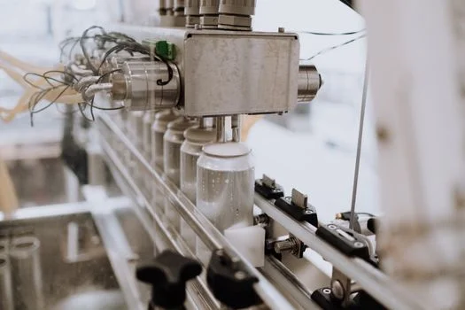
Digital twin ROI in semiconductor wastewater treatment is built on three quantified levers: chemical dosing, membrane life, and energy. A twin is a high-fidelity simulation of the entire water system — ultrapure production, reclaim loops, tool discharge, treatment, outfalls — fed by live data. Engineers use it to predict behavior, test scenarios, and optimize operations before touching the plant.
The savings numbers are specific. Accurate simulation of chemical interactions trims coagulant and flocculant use by 15–20% in pretreatment. Predictive maintenance optimizes cleaning cycles and extends RO membrane life by 2–3 years. Annual savings reach 20–25% on energy and chemical lines combined. A 500 m³/h fab running a digital twin reported a 40% reduction in freshwater demand and roughly $250,000 per year in chemical cost savings.
Implementation follows a five-step approach:
- Data Integration: Consolidating data from SCADA systems, LIMS (Laboratory Information Management Systems), ERP (Enterprise Resource Planning), and process sensors to create a comprehensive data foundation.
- Model Calibration: Developing and validating the digital twin model against historical and real-time operational data to ensure accuracy and reliability.
- Scenario Testing: Running simulations for various operating conditions, tool discharge patterns, and potential upsets to identify optimal treatment strategies and emergency response protocols.
- Real-time Monitoring: Continuously feeding live data into the digital twin to provide operators with up-to-the-minute insights and performance dashboards.
- Predictive Maintenance: Utilizing the model's predictive capabilities to forecast equipment failures, schedule maintenance proactively, and minimize unplanned downtime.
This framework keeps the twin a practical operating tool rather than a shelf model. Fabs that skip calibration discipline — step 2 — routinely end up with dashboards nobody trusts, and the OPEX savings never materialize.
ZLD vs. Partial Reuse: Cost-Benefit Analysis for Semiconductor Fabs
Zero Liquid Discharge (ZLD) versus partial reuse is a site-by-site decision driven by regulation, water availability, and capital economics. For a 500 m³/h fab, ZLD CAPEX runs $5 million to $10 million with OPEX of $1.2 million to $1.8 million per year, reflecting energy-intensive evaporation and crystallization. A partial reuse system built on high-recovery RO and ultrafiltration costs $3 million to $6 million with OPEX of $800,000 to $1.2 million per year.
Energy separates the two options sharply: ZLD often draws 3–5 kWh/m³ against 2–4 kWh/m³ for high-recovery RO. Partial reuse, typically achieving 90%+ recovery, is the economically feasible choice where discharge regulations remain moderate; ZLD is increasingly mandated in water-scarce regions such as parts of Asia and the Middle East, where eliminating liquid discharge and securing water self-sufficiency justify the premium.
Campus layout adds a strategic layer. Our evaluation of centralised and decentralised wastewater treatment strategies for semiconductor facilities compares both routes with real performance data, and the answer changes with footprint and tool mix.
Holding time before discharge is another budget line; our Jubail project notes on industrial waste discharge time of water show how large industrial parks schedule retention against reuse targets. Fabs also discharge acid and alkaline cleaning streams — the neutralization train is covered in How to Treat Acid-Alkaline Wastewater: 2026 Engineering Specs, Hybrid.
| Factor | Consider ZLD if... | Consider Partial Reuse if... |
|---|---|---|
| Regulatory Pressure | Zero-discharge mandates are in place or imminent; extremely strict discharge limits for TDS, salts, or specific ions. | Discharge limits are manageable with advanced treatment; no absolute zero-discharge requirement. |
| Water Scarcity | Local water sources are severely limited or prohibitively expensive; high reliance on purchased water. | Water availability is moderate; partial reuse significantly reduces reliance on freshwater. |
| CAPEX Budget | Sufficient capital is available for a high upfront investment; long-term water security is paramount. | Capital budget is more constrained; focus on maximizing ROI from water savings. |
| OPEX Tolerance | Higher operational costs are acceptable for complete water reclamation and waste minimization. | Preference for lower operational costs with significant, but not total, water recovery. |
| Brine Disposal | On-site brine concentration and solidification are feasible and permitted; no suitable deep-well injection or evaporation pond options. | Disposal of brine concentrate to a regulated facility or evaporation pond is viable. |
For fabs prioritizing maximum recovery in challenging environments, high-recovery RO systems anchor both partial reuse and ZLD strategies — the difference lies in what happens to the brine downstream.
Next Steps: Characterize, Pilot, Quote
Fab engineering teams with a characterized effluent profile can move from this spec sheet to a budgeted design in one pilot cycle. Start with contaminant profiling across production peaks, pilot the candidate train, then price the hybrid against the ZLD decision table. Send your flow rate and pollutant parameters through our quotation desk for a technology-matched design and cost estimate.
Frequently Asked Questions
Common questions from fab engineers and EPC evaluators on semiconductor water treatment.
What are the typical flow rates for semiconductor wastewater treatment systems?
Typical semiconductor fab wastewater flows range from 200 m³/h to over 500 m³/h, set by fab size and production intensity. A 200 m³/h fab usually runs one hybrid train, while larger sites split flows into parallel trains so maintenance never stops the whole system. Tool cleanings batch-discharge, so equalization volume is sized around the peak hour, not the daily average.
How effective are DAF systems for removing photoresist from wastewater?
DAF systems achieve 90%+ removal of suspended photoresist particles by capturing them in the float sludge. Dissolved photoresist components pass through, so polishing with AOP or RO is needed where dissolved-organics limits apply. In practice DAF earns its slot as stage one: it shields membranes from the sticky suspended fraction that causes most fouling events in fab trains.
What is the typical recovery rate for RO systems in semiconductor applications?
High-recovery RO systems in semiconductor wastewater service are designed for recovery rates of 85% to 95%, maximizing reuse while concentrating dissolved solids into a manageable brine. Pushing above that band raises scaling risk on silica and fluoride, which is why antiscalant dosing and softening precede the membranes. The 95%+ reuse figures for full hybrid trains combine RO recovery with recycle routing.
Can MBR systems fully treat TMAH wastewater?
MBR systems biodegrade a significant fraction of TMAH, but complete removal typically requires pairing with AOP or RO, especially against stringent discharge limits. TMAH arriving between 50–500 mg/L responds well to acclimatized biology; shock loads do not. Plants targeting sub-ppm effluent run MBR as the middle stage and let oxidation or membranes finish the job.
What are the primary drivers for implementing ZLD in semiconductor fabs?
The primary drivers for ZLD are stringent regulatory discharge limits, severe water scarcity, and corporate sustainability commitments. In water-stressed regions across parts of Asia and the Middle East, zero-discharge mandates leave no alternative. Where discharge permits remain available, most fabs choose partial reuse at 90%+ recovery and defer ZLD until regulation or water economics force the step.
How do digital twins impact the OPEX of wastewater treatment?
Digital twins cut OPEX through three levers: optimized chemical dosing worth 15–20% less coagulant and flocculant, predictive maintenance that extends RO membrane life by 2–3 years, and energy scheduling that trims consumption. Reported results at a 500 m³/h fab include a 40% freshwater-demand reduction and roughly $250,000 per year in chemical savings — 20–25% on the affected annual OPEX lines.
What is the estimated CAPEX for a hybrid DAF-RO-MBR system for a 500 m³/h fab?
The estimated CAPEX for a hybrid DAF-RO-MBR system at a 500 m³/h fab ranges from $3 million to $6 million, depending on configuration and site works. That band matches partial-reuse pricing; full ZLD with evaporation and crystallization runs $5 million to $10 million instead. Site civil works and reuse routing usually decide where a project lands inside the band.
How can I determine the best treatment technology for my fab's specific wastewater?
A comprehensive influent characterization followed by pilot testing is the only reliable way to select the treatment train, because fab wastewater varies with proprietary chemistries. Profile TMAH, fluoride, metals, and organics across production peaks first, then pilot the candidate train before committing capital. Suppliers with semiconductor references can shorten the loop — HydropureWater sizes hybrid DAF-RO-MBR trains directly from characterization data.
Are there specific regulations for TMAH in semiconductor wastewater?
TMAH is usually regulated indirectly through COD limits or specific local ordinances, because its high organic load and toxicity drive both parameters. General limits on COD, TSS, and heavy metals still apply at the outfall. Confirm the local rule early: some jurisdictions list TMAH explicitly, which turns the polishing stage from optional into mandatory before the permit is granted.
How does photoresist wastewater differ from other semiconductor wastewater streams?
Photoresist wastewater differs from other fab streams by combining high suspended solids, organic polymers, and solvents in a single flow. That mix resists single-stage treatment: physical separation captures the particles, while dissolved polymers and solvents need chemical or biological polishing. Segregating photoresist drains at source keeps their load off the general sewer and shrinks every downstream stage of the train.
Further Reading
Explore these in-depth articles on related wastewater treatment topics: