
Decanter Centrifuge Design: Three Force Zones That Set Performance
Decanter centrifuge design for continuous sludge duty rests on three bowl zones and a G-force band matched to the feed. Typical industrial units deliver 1500–4000×g, hold differential speed at 5–80 RPM, and produce 18–35% dry solids (DS) cake when polymer conditioning is correct. Capture rate targets are usually ≥95% with centrate TSS often held at 200–500 mg/L under stable feed.
A horizontal decanter centrifuge separates solids from one or two liquid phases by spinning a conical-cylindrical bowl at 1500–4000×g. An internal screw conveyor, running a few RPM slower than the bowl, plows compacted cake up a conical beach. Clarified liquid overflows dam plates at the opposite end. Feed solids, particle size, target cake dryness, and required G-force drive the selection.
Inside the bowl, three functional zones govern performance. The clarification zone occupies the cylindrical section where feed enters and liquid–solid separation begins. Residence time here is 10–40 seconds for typical dewatering duties. G-force acts perpendicular to the bowl wall to migrate denser particles outward.
The transition zone begins where the cone starts. There the clarified liquid (the "pond") reaches its adjustable depth set by interchangeable weir rings. The drying or beach zone is the conical section where dewatered cake moves up an inclined surface toward the solids discharge port. Cake residence time here is typically 5–20 seconds, and the cake reaches 18–35% dry solids (DS) before exiting.
Bowl and scroll rotate in the same direction with a differential speed (Δn) window of 5–80 RPM. Counter-current designs exist but are rare in industrial dewatering. Dam plates (weir rings) at the liquid end set pond depth. A deeper pond extends clarification residence time and improves solids capture but shortens beach length.
A shallower pond produces drier cake at the cost of higher centrate turbidity. Pond depth is one of the few parameters an operator can change in minutes by swapping rings. It is the first tuning step during commissioning. Most plants we size for municipal or food biosolids start with a mid-depth pond and trim beach length only after centrate TSS stabilizes.
G-Force, Bowl Diameter, and Rotational Speed: The Sizing Triangle
G-force is the single most important sizing variable for bowl selection. It is calculated as G = 1.12 × 10⁻⁵ × r × n², where r is the bowl inner radius in millimetres and n is the bowl speed in RPM. For a 350 mm inner-diameter bowl (r = 175 mm) running at 4000 RPM, G = 1.12 × 10⁻⁵ × 175 × (4000)² ≈ 31,360 m/s², or roughly 3200×g. Larger-diameter bowls reach the same G-force at lower RPM.
A 760 mm bowl (r = 380 mm) needs only ~2700 RPM to deliver 3000×g. That reduces bearing load, noise (typically 78–85 dB(A) at 1 m for mid-size decanters), and scroll-flight wear. Industrial G-force bands cluster into three practical classes. The engineer's first decision is which band matches the feed:
| Design Class | G-Force Range | Typical Bowl Speed | Common Applications |
|---|---|---|---|
| Low-G (biosolids) | 1500–2000×g | 2200–2800 RPM | Waste-activated sludge, digestate, food biosolids |
| Mid-G (industrial) | 2000–3000×g | 2800–3500 RPM | Oily sludge, dairy, pulp & paper, chemical clarifier underflow |
| High-G (mineral/chemical) | 3000–4000×g | 3200–4000 RPM | Kaolin, calcium carbonate, drilling mud, TiO₂, salt slurries |
The trade-off is not free. Doubling G-force from 2000×g to 4000×g roughly doubles power draw (typical main-drive power 22–110 kW for mid-size units). Abrasion on scroll flights rises by a factor of 2–3× in mineral service, and bearing-class ratings must increase. For waste-activated sludge, most plants we size stay at 2000–2500×g with polymer rather than the 4000×g ceiling.
Bowl Geometry, Beach Angle, and Scroll Pitch
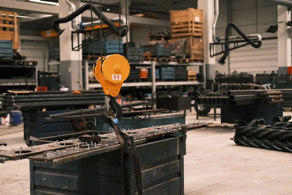
Static bowl geometry sets the upper bound on cake transport and dryness independent of rotational speed. The beach angle — the incline of the conical section relative to the bowl axis — typically ranges from 6° to 15°. Soft, compressible biological sludge (waste-activated, anaerobic digestate) operates at 6°–8° because the cake must ride up a gentler slope without re-fluidizing. Free-draining mineral or crystalline slurries tolerate 10°–15° because the cake is granular and self-supporting.
The L/D ratio (bowl length to bowl diameter) governs residence time versus footprint. Dewatering bowls typically run 3:1 to 4:1. A 30-inch (760 mm) bowl with a 4:1 L/D is roughly 3 m long. Clarification duties push L/D to 5:1 to maximise hydraulic residence time.
Conical beach length is usually 25–40% of total bowl length. A longer beach improves dryness by giving the cake more time under compaction. It also raises the G-force required to transport a given mass flow up the slope. Scroll pitch and lead angle are matched to the differential-speed range.
A coarser pitch (lower helix angle) moves more cake per revolution but requires higher torque. The rule of thumb is to size the scroll drivetrain for 80–120% of expected solids torque so a feed spike from 4% to 8% DS does not stall the drive. Scroll tip clearance to the bowl wall is typically 0.5–2.0 mm depending on bowl size. Tighter clearance improves solids capture but raises tramp-material damage risk.
Differential Speed, Hydraulic Back-Drive, and Solids Throughput
Differential speed (Δn) — the slip between bowl and scroll — is the dynamic lever operators use to handle feed variability. For dewatering, Δn runs 5–80 RPM. Biological sludge runs at 5–15 RPM for slow transport and maximum compaction. Oily or fibrous sludge sits at 20–40 RPM, while mineral slurry uses 40–80 RPM.
Set Δn wrong and the failure mode is immediate. Too low: cake packs the beach zone, the scroll stalls, and main-drive current spikes. Vibration trips then shut the unit down — typical trip setpoint is 8–12 mm/s RMS at the bearing housing. Too high: the scroll re-mixes cake with clarified liquid just before discharge.
Cake moisture then rises by 3–5 percentage points. Centrate TSS climbs from a normal 200–500 mg/L to 2000+ mg/L. Capture rate — typically specified at ≥95% — collapses in tandem. Modern decanters solve this with hydraulic back-drive or VFD-controlled secondary drives that adjust Δn on the fly.
That drive upgrade is the biggest operational gain over legacy fixed-gear units. An operator can hold constant cake dryness while feed solids swing from ~2% to ~8% DS. Throughput scales with the sigma-value concept — capacity ∝ G-force × residence time. Doubling G at constant residence time roughly doubles throughput at the same capture rate, and halving L/D halves capacity.
A mid-G 30-inch bowl typically processes 15–40 m³/h of 2–5% feed sludge.
How Can a Decanter Improve Biosludge Dewatering?
Biosludge dewatering on a horizontal decanter improves when Low-G duty (1500–2500×g), soft beach angles (6°–8°), and low Δn (5–15 RPM) are paired with cationic polymer at 2–6 kg/t DS. Thin waste-activated sludge without thickening often exits near 18–22% DS. Well-conditioned digestate can reach the upper 18–35% DS band. Upstream thickening and rag control usually move results more than pushing bowl speed toward the 4000×g ceiling.
Operators chasing drier municipal cake should lock polymer age time, then trim pond depth before raising RPM. For food or digester streams that already sit near the wet end of the band, see our notes on digested sludge dewatering 18% cake for feed-specific targets. Pairing the centrifuge with a scoped sludge thickener installation and commissioning package keeps feed solids inside the 2–5% DS window most mid-size bowls expect.
Polymer Conditioning and Feed Preparation

A correctly sized decanter still produces wet cake and high centrate TSS if the upstream polymer conditioning is wrong. Anionic or cationic polyacrylamide (PAM) flocculant is standard, with typical dosing of 2–15 kg dry polymer per ton dry solids depending on sludge type. Use 2–5 kg/t DS for thickened waste-activated sludge with cationic PAM. Oily refinery sludge often needs 5–10 kg/t DS, and fine mineral tailings with anionic PAM can reach 10–15 kg/t DS.
Floc strength is the trade-off. Strong flocs survive scroll transport and produce drier cake but trap water internally and lower capture rate. Weak flocs break in the scroll and re-enter the centrate. The optimum is sludge-specific and confirmed only by jar testing followed by on-site pilot.
Inline polymer make-down units age emulsion polymer for 30–60 minutes before dosing (dry polymer ages faster, ~15–20 min). The make-down skids must be sized to the centrifuge feed flow, not just to the polymer pump capacity. Otherwise flocs will be under- or over-aged at the injection point. Fibrous and raggy feeds — common in municipal mixed sludge and some food-industry streams — must be cut upstream.
A rotary bar screen with 3–6 mm aperture ahead of the centrifuge prevents rag entanglement around the scroll. That failure mode is the single most common unplanned-downtime cause on municipal decanter installations.
Material Selection and Wear Protection
Bowl metallurgy is chosen to balance corrosion, abrasion, and sanitisation. The bowl body is typically duplex stainless steel (1.4462 / SAF 2205) for industrial and oily feeds. Its 450 MPa yield strength allows thinner walls at high RPM, and its PREN ~35 handles chlorides better than 316L. Food, dairy, and pharma duties default to 316L for cleanability and CIP compatibility, accepting higher wall thickness or lower RPM.
Highly corrosive chemical feeds (strong acids, brines) escalate to Hastelloy C-276 or alloy 625 on wetted parts. Scroll flights take the most abrasion. The leading edge is hard-faced with Stellite 6 or tungsten carbide. High-abrasion duties (mineral, drilling mud) use replaceable tile segments that can be swapped in 4–8 hours without a full scroll rebuild.
Solids discharge ports are lined with ceramic or polyurethane bushings where the cake exits, since that is the single highest-wear point on the machine. Shaft seals are typically cartridge-type mechanical seals with tungsten carbide faces for chemical or oily feeds. Lip seals are acceptable only on biosolids duty where dry running and clean-in-place are not required.
Decanter Centrifuge vs. Alternative Dewatering Technologies
The decanter is rarely the only option on the table. A defensible capex review needs the comparison numbers below before the RFQ is issued:
| Parameter | Decanter Centrifuge | Plate & Frame Filter Press | Belt Press | Screw Press |
|---|---|---|---|---|
| Operation | Continuous, enclosed | Batch, open or enclosed | Continuous, open | Continuous, enclosed |
| Cake dryness (% DS) | 18–35% | 30–45% | 15–22% | 18–28% |
| Solids capture rate | ≥95% | ≥98% | 85–95% | 90–95% |
| Footprint | Compact | Large | Medium-large | Compact |
| Typical capex (relative) | High | Medium | Low–medium | Low–medium |
| Handles oily/fibrous feed | Yes | Limited | Poor | Limited |
| Odor control | Inherent (enclosed) | Optional enclosure | Poor | Good |
Filter presses reach the driest cake (30–45% DS) but are batch — a 1.5–3 hour cycle per batch — with larger footprint and higher labour cost. The Plate and Frame Filter Press for Sludge Dewatering remains the usual batch alternative when cake dryness above ~35% DS is mandatory. Belt presses have the lowest capex and power draw (typically 2–5 kW versus 22–110 kW for a decanter). They cannot handle oily or fibrous feeds and produce wetter cake.
For open-belt selection detail, compare belt press sludge dewatering against enclosed continuous machines. Screw presses sit between belt and decanter on cost. They are gaining share in small municipal plants under ~3% feed solids, but cannot match decanter throughput on industrial slurries.
Budget reviews should separate machine price from polymer, power, and disposal. A full sludge dewatering cost comparison across technologies, plus the sludge dewatering machine buyer's guide, helps size OPEX before the RFQ is issued.
What Is the Best Centrifuge for Municipal Sludge?
Municipal sludge plants usually shortlist a Low-G to mid-G horizontal decanter at 1500–2500×g. Spec a 6°–8° beach, duplex or 316L bowl, hydraulic back-drive, and cationic PAM at 2–6 kg/t DS. Disk-stack or laboratory centrifuges suit low-solids clarification, not 2–8% DS continuous cake discharge. Capture ≥95% and cake 18–35% DS are realistic when feed is screened and thickened.
Municipal mixed sludge with rags still needs a 3–6 mm screen ahead of the scroll. Plants under roughly 3% feed solids sometimes shortlist a screw press on capex. Oily or fibrous loads swing the decision back to a decanter. Non-standard industrial cousins of municipal biosolids — for example plastic washwater sludge — follow the same checklist in the plastic manufacturing wastewater sludge treatment guide.
Decanter Centrifuge Selection Checklist
Decanter selection for sludge dewatering starts with feed solids, target cake % DS, and G-force class before materials and drives are locked.
- Define the feed. Solids concentration (%), particle size distribution (typically D50 reported at µm scale), oil and grease content (%), pH, temperature (°C), and abrasiveness. These five numbers eliminate roughly half the candidate machines.
- Set the performance targets. Cake dryness (% DS) and centrate quality (TSS in mg/L). Typical industrial targets are ≥95% solids capture rate, ≤100 mg/L centrate TSS for reuse, ≤50 mg/L for direct discharge.
- Choose the design class. Low-G biosolids (1500–2000×g), mid-G industrial (2000–3000×g), or high-G mineral/chemical (3000–4000×g) — refer to the parameter table in the G-force section.
- Specify materials and drives. Duplex SS, 316L, or alloy upgrade; main-drive VFD for feed turndown; hydraulic back-drive for Δn flexibility; mechanical seal type matched to feed chemistry.
- Confirm downstream cake handling. Screw conveyor, cake pump, or skip hoist — and confirm it can move cake at the target % DS without choking. Polymer make-down skid and upstream thickening should be scoped together.
- Request vendor guarantees with a pilot or rental trial. Specify power (kWh per ton DS), polymer (kg per ton DS), and water consumption per ton DS in the RFQ; do not accept generic "suitable for application" language.
Who this is for: plant engineers and EPC teams sizing continuous enclosed dewatering for 2–8% DS feeds that need ≥95% capture. Who should look elsewhere: sites that need >35% DS cake on a batch cycle, or very small plants where a low-capex belt or screw press already meets dryness and footprint. Next step: send feed solids, target cake % DS, and centrate TSS limits with your decanter sizing inquiry so drive power and polymer dose can be checked against a pilot curve.
Frequently Asked Questions
What G-force does a decanter centrifuge produce?
Industrial decanters operate between 1500×g and 4000×g, calculated as G = 1.12 × 10⁻⁵ × r × n². A 30-inch bowl at 3000 RPM delivers roughly 1800×g; the same bowl at 4000 RPM reaches about 3200×g. Duty class then narrows the band: biosolids usually stay near 1500–2500×g, while mineral slurries push toward 3000–4000×g.
How does a decanter centrifuge differ from a standard centrifuge?
A decanter is a horizontal scroll-discharge unit designed for continuous solids handling at high feed solids (2–8% DS typical). A standard laboratory or disk-stack centrifuge is usually vertical, batch-fed, and intended for liquid clarification at low solids loading. Municipal and industrial sludge plants therefore specify decanters when cake must leave the machine without stopping the feed.
What cake dryness can a decanter achieve on waste-activated sludge?
Waste-activated sludge typically reaches 18–35% DS at 2000–2500×g with cationic polymer dosing of 3–6 kg/t DS. Well-conditioned digestate can reach the upper end, while thin WAS without thickening sits near 18–22%. Polymer age time and pond depth usually move dryness more than raising bowl speed alone.
Why is the scroll speed different from the bowl speed?
The differential (5–80 RPM lower than the bowl) drives cake transport up the beach without re-mixing the just-clarified liquid. Both rotate in the same direction; counter-current designs exist but are uncommon in dewatering. Too low a Δn packs the beach and trips on vibration; too high a Δn raises cake moisture by 3–5 points.
Can a decanter centrifuge handle oily sludge or rags?
Yes, with tungsten-carbide mechanical seals, hard-faced scroll flights, and upstream screening (typically a 3–6 mm rotary bar screen) to prevent rag entanglement. Oily refinery and tank-bottom sludges are a common decanter application at 2000–3000×g. Without screening, rag wrap around the scroll remains the leading cause of unplanned municipal downtime.