
Why Most Thickener Startups Fail in the First 72 Hours
Skipping the civil tolerance check is the single most expensive mistake a first-time commissioning engineer makes on a sludge thickener installation and commissioning project — and the failure rarely shows up as a structural defect. It shows up as poor capture, polymer overdose, or belt drift on day three of the SAT, by which point the grout has cured and the root cause is buried. Field data from municipal startups between 2024-2026 shows that roughly 60–70% of first-week thickener faults trace back to four pre-commissioning gaps: foundation out of tolerance, belt or drum misalignment, polymer dose set by guess rather than jar test, and operators who have never seen that specific control logic before.
Four root-cause categories explain almost every early failure. Civil: the foundation is out of level by more than the supplier's tolerance, so the thickener frame twists and rollers go out of parallel within hours of start-up. Mechanical: belt tracking or drum concentricity was never verified because the contractor bolted down and grouted before checking alignment. Process: the polymer dose was set to the supplier default instead of the jar-test optimum, with supplier defaults typically running 30–50% over the real optimum. Operational: the day-shift operator has had no hands-on time on the actual HMI before the SAT clock starts.
The Ruhrverband Arnsberg-Wildshausen installation (Alfa Laval case study) is the counter-example worth remembering: a properly containerized skid with pre-wired controls, internal polymer system, and factory-tested PLC reduced the field installation to mechanical setting and polymer calibration — shifting the risk surface from site to FAT. That shift is why factory integration now carries a 10–20% cost premium on most bids, and why the contractor who skips the civil check on a non-containerized unit is the one writing the punch list.
One parameter decides more startups than any other: the 3–10 g/kg polymer dose. If that number is guessed instead of jar-tested against the actual feed sludge, capture rate falls below 90% within hours and the operator compensates by adding more polymer — which makes the carryover worse, not better. The SAT-as-handover principle governs everything that follows: the 72-hour continuous run is the contractual trigger, not the truck's arrival time. Treat the delivery note as logistics, not acceptance.
Thickener Type Comparison: Belt, Drum, and DAF
Before any commissioning checklist makes sense, the engineer on site needs to confirm which thickener type is bolted to the foundation — the critical path through Phases 2 to 4 is different for each. The table below summarizes the three common types, their design operating windows, and the commissioning parameter that decides whether the unit will pass SAT. If the unit on site is a dissolved-air unit, the DAF thickener and flotation system reference page gives the saturator and recycle pump detail not repeated here.
| Parameter | Gravity Belt Thickener (GBT) | Rotary Drum Thickener (RDT) | Dissolved Air Flotation (DAF) Thickener |
|---|---|---|---|
| Feed TS range | 0.5–1.5% | 0.5–2.0% | 0.3–1.0% |
| Thickened DS target | 4–8% | 3–6% | 3–5% |
| Polymer dose (g/kg DS) | 3–10 | 3–8 | 2–6 |
| Hydraulic loading | 10–25 m³/m·h (belt width) | 20–40 m³/m²·h (drum area) | 5–25 m³/m²·h (tank area) |
| Washwater / recycle | 4–6 bar, 50–150 L/m·h | Spray 2–4 bar | Recycle 50–100% of feed, saturator 4–6 bar |
| Key commissioning check | Belt tracking + washwater pressure | Drum runout + spray bar alignment | Air-to-solids ratio 0.02–0.06 kg air/kg TSS |
| Typical footprint | Medium (6–12 m long) | Compact (1–3 m diameter) | Medium-large tank |
| Order-of-magnitude cost | US$4,000–60,000 per set | US$15,000–80,000 per set | US$2,000–8,000 per set (small DAF) |
Decision rule for the field engineer: choose a gravity belt thickener for primary sludge thickening at medium-to-large plants where 4–8% thickened DS is the target; choose a rotary drum for space-constrained retrofits and smaller flow rates; choose DAF for waste activated sludge with FOG or industrial loads where the air-to-solids ratio can be independently controlled. The cost bands are B2B catalog order-of-magnitude only — never quote them as a fixed price.
Phase 1 — Pre-Arrival Engineering and Civil Preparation
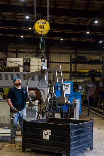
Every minute spent on civil preparation before the truck arrives saves an hour of rework after the grout cures. The four checks in this phase are non-negotiable; if any one of them is missed, do not start the mechanical installation.
- Foundation levelness. Verify the foundation slab to within ±3 mm over any 3 m span and ±6 mm across the full skid footprint, measured with a precision optical or digital level — not a string line and a hand level. Out-of-level foundations cause belt tracking drift, drum eccentric loading, and DAF tank weir imbalance, and none of these can be corrected by shimming after the unit is grouted.
- Service connections. Confirm the feed sludge pipe is DN-sized to a velocity of ≤1.5 m/s (typically DN80–DN150 for a single thickener), the thickened sludge outlet is routed to storage or digestion, washwater supply is at 4–6 bar with a minimum 50 L/min capacity, the polymer line terminates within 3 m of the make-up unit, and a floor drain is within 1 m of the skid perimeter.
- Electrical supply. Verify the incoming supply matches the nameplate — typically 380–415 V, 3-phase, 50 Hz for IEC markets, with a dedicated isolator located to allow 1.0 m of front access to the control cabinet per IEC 60204. Confirm the cable cross-section and breaker rating against the nameplate full-load amps plus 25% margin.
- FAT document review. Before delivery, confirm the nameplate data, P&ID, electrical schematics, PLC program backup, and the I/O list are on site and have been read by the commissioning engineer. Skid-mounted units with pre-wired controls shift most of the risk to the FAT; on a non-containerized unit, the contractor owns all of it.
Hoisting and rigging are the fifth item, and the one most often improvised: confirm the lifting lugs are present and rated for the assembled mass, that the crane can reach over any overhead pipe racks, and that the route from the truck to the foundation is clear of obstructions and rated for the loaded truck weight. A foundation pit that floods overnight is the most common Phase 1 surprise — pump it dry before the truck arrives, not after.
Phase 2 — Mechanical Installation and Alignment
Day one and two of commissioning are mechanical. The sequence matters: level, grout, cure, then align. Reversing the order is the most common reason anchor bolts fail their torque check at SAT.
- Set and level. Place the skid on adjustable shim packs at each anchor point and level to ±0.5 mm/m across both axes using the precision level from Phase 1. Do not torque the anchor bolts or apply grout until the level reading is stable for at least 30 minutes.
- Grout. Use a non-shrink cementitious grout (typical products: Fosroc Conbextra HF, Masterflow 648, or equivalent) and fill the baseplate void completely. Do not bolt the anchor fasteners to final torque until the grout has cured for a minimum of 48 hours; premature loading cracks the grout and shifts the frame.
- Type-specific alignment.
- Gravity belt: align the gravity-deck and pressure-zone rollers parallel within 1 mm across the full belt width using a dial gauge on the roller shafts; check belt tracking by hand-rotation before connecting the drive; verify belt tension at 0.5–1.0% elongation per the supplier's tension chart.
- Rotary drum: verify drum-to-chassis concentricity with a dial indicator — total indicated runout should be less than 0.1 mm at the drum face; confirm the internal spray bar is unobstructed, oriented along the drum axis, and the nozzles are not clogged.
- DAF: level the flotation tank on its own supports (it is rarely on the main skid), verify the recycle pump suction is flooded under all operating levels, and set the saturator pressure relief to the design value, typically 4–6 bar — adjust before the first run, not during.
- Torque and record. Torque every anchor bolt to the supplier's specification using a calibrated wrench, and record the value, the date, and the installer on the installation sheet. Per standard contract practice, an unrecorded torque is treated as not done at the SAT walkdown — write it down even if the supplier says "just snug it up."
Phase 3 — Electrical, Controls, and Polymer System Setup

Phase 3 is where roughly 80% of field rework originates, and almost all of it is wiring or polymer dose — not the equipment itself. The pace here is slower than Phase 2; do not rush it.
- Continuity and insulation test. Megger every motor winding and instrument loop to the panel before energizing, and record insulation resistance (typically >100 MΩ at 500 V for a healthy motor) on the loop check sheet. A grounded motor winding discovered after the contactor is closed is a Phase 3 delay measured in days, not hours.
- PLC I/O verification. Simulate every digital input (limit switches, level switches, pressure switches) and force every analog output (VFD speed reference, polymer pump stroke) to confirm the wiring matches the I/O list shipped from the FAT. A crossed wire on a polymer pump stroke signal is invisible until the dose curve fails at SAT.
- Polymer system calibration. Prime the polymer pump with water, then verify the dose curve at three points (low, mid, design flow) using the calibration beaker method — measure stroke length or pump RPM against pumped volume per minute, and plot the curve. The linear fit should have an R² > 0.98; a lower R² means a worn pump or a sticky check valve.
- On-site jar testing. Run 5–6 polymer doses on the actual feed sludge to identify the optimum dose and maturation time. Typical maturation is 30–90 seconds for belt and drum thickeners, near-instant for DAF. The optimum dose is the one that gives the highest supernatant clarity at the lowest polymer consumption — not the one that gives the thickest floc. The automatic polymer dosing skid documentation usually includes a jar-test protocol; follow it.
- Set the operating dose. Set the polymer dose to the jar-test optimum, not the supplier's default. Field experience across 2024–2026 municipal startups shows supplier defaults run 30–50% over the real optimum on waste activated sludge feeds — overdosing costs money, and on DAF units it can also collapse the air-to-solids ratio by changing the bubble attachment surface.
| Parameter | Acceptance target | Verification method |
|---|---|---|
| Insulation resistance (motors) | >100 MΩ at 500 V | Megger test, recorded on loop sheet |
| PLC I/O | 100% of points verified | Simulate inputs, force outputs, sign-off sheet |
| Polymer pump calibration R² | >0.98 across 3 points | Beaker method, linear regression |
| Jar-test optimum dose | 3–10 g/kg DS (belt/drum); 2–6 g/kg DS (DAF) | 5–6 dose jars on actual feed sludge |
| Polymer maturation time | 30–90 s (belt/drum); near-instant (DAF) | Visual floc formation in jar |
Phase 4 — Performance Test and SAT Acceptance Criteria
The 72-hour site acceptance test is the legal handover, not the truck's arrival time. Run it on actual site sludge — not on clean water — and do not start the clock until the unit has been on feed for at least 4 hours at design rate. The acceptance numbers below are the contractual pass/fail line; everything else is commentary.
- Duration and logging. Run the thickener on actual site sludge for a minimum of 72 hours continuously. Record feed TS, thickened TS, subnat/float TSS, capture rate, polymer consumption, and washwater or recycle flow at 4-hour intervals. If the unit trips or stops for more than 30 minutes during the 72-hour window, the clock restarts.
- Acceptance targets.
- Thickened DS within design range: belt 4–8%, drum 3–6%, DAF 3–5%.
- Solids capture rate ≥95% across the 72-hour window, calculated as (thickened flow × thickened TS) ÷ (feed flow × feed TS).
- Polymer consumption within ±10% of the jar-test design dose.
- No scum overflow, no belt drift, no saturator pressure deviation > ±0.3 bar from setpoint.
- Hydraulic overload test. Confirm the unit can operate continuously at 110% of design feed rate for at least 1 hour without subnat carryover or polymer break-through. This is the test that catches the oversize feed pump before it becomes a warranty dispute.
- Sign-off discipline. Document every parameter on the SAT sheet with operator signature, supervisor signature, and date. The SAT sheet, not the delivery note, is the legal handover document. If any acceptance criterion fails, do not "accept with reservations" — issue a punch list with a hard rework date before any retention release. A punch list without a date is not a punch list.
For plants installing a downstream dewatering unit, the thickened sludge DS verified in Phase 4 is the feed condition for the next commissioning — the downstream sludge dewatering press has its own acceptance window and depends on the thickener hitting its 4–8% (belt) or 3–6% (drum) target to pass.
Five Common Commissioning Failures and How to Diagnose Them

The same five failures show up on day two and three of almost every thickener startup. Diagnose them in this order before touching the equipment.
- Belt tracking off to one side. Before adjusting the tracking mechanism, check roller parallelism and belt tension. A tracking fault that appears on day two is almost always a Phase 2 alignment oversight — the rollers are out of parallel by more than 1 mm or the belt is over-tensioned. Re-shim the rollers, do not chase the belt with the tracking adjuster.
- Low capture rate with clear subnat. This sounds like a polymer problem but is usually a dose problem. Repeat the jar test on a fresh feed sample before touching the equipment — the feed sludge characteristics often shift in the first 48 hours of plant startup, and the dose set on day one may no longer be optimal on day three.
- Scum overflow on a DAF unit. Verify the air-to-solids ratio is in the 0.02–0.06 kg air/kg TSS range and confirm the saturator pressure is at the design value. The most common root cause is saturator water temperature too low (below ~10 °C), which reduces air solubility and collapses the bubble population — warm the saturator feed or install a recycle-water tempering line.
- Excessive polymer consumption. Check the polymer transfer pump type and the static mixer condition. High shear in a centrifugal transfer pump or a clogged static mixer can destroy polymer chain length and force the operator to over-dose to compensate. Switch to a positive-displacement transfer pump and clean the mixer before adjusting the dose.
- Hydraulic surge and intermittent feed. The feed pump is oversized for the thickener capacity, or the feed line has air pockets. Install a feed well at the thickener inlet, add a de-aeration point at the high spot in the feed line, or trim the feed pump impeller. Chasing surge with the VFD ramp rate will mask the symptom for a day and then return.
Frequently Asked Questions
What is the typical thickened sludge DS from a gravity belt thickener?
A gravity belt thickener typically produces 4–8% thickened dry solids from a feed of 0.5–1.5% TS, depending on belt speed, polymer dose, and sludge type. This is the design target used as the SAT acceptance criterion in Phase 4 of the commissioning procedure. If the unit cannot hold 4% DS across the 72-hour window, the polymer dose or belt speed is set incorrectly.
How long does thickener commissioning take from delivery to SAT sign-off?
For a non-containerized unit, allow 5–7 working days: 1 day for mechanical setting, 1 day waiting for grout cure, 1–2 days for electrical and polymer calibration, and 3 days for the 72-hour SAT. Containerized skids with pre-wired controls typically compress this to 3–4 days because the FAT has already covered most of the electrical and controls scope.
What polymer dose should I use for a rotary drum thickener on waste activated sludge?
For waste activated sludge, jar testing typically returns 3–8 g/kg DS of polyacrylamide, with a maturation time of 30–90 seconds. Always set the operating dose to the jar-test optimum, not the supplier's default — supplier defaults run 30–50% over the real optimum on WAS feeds. The dose should be re-verified weekly during the first month of operation.
What is the air-to-solids ratio for a DAF thickener?
The design range is 0.02–0.06 kg air/kg TSS, with the saturator operating at 4–6 bar and recycle water at 50–100% of feed flow. Below 0.02 kg/kg, capture rate drops sharply; above 0.06 kg/kg, the operator is wasting compressed air and disrupting the float layer. Verify the ratio during the SAT at 110% of design feed rate.
What is the most common reason thickener SAT fails on the first attempt?
Solids capture rate below 95%, almost always caused by a polymer dose set to the supplier default rather than the jar-test optimum. The fix is to repeat the jar test on fresh feed, set the dose to the new optimum, and re-run the 72-hour window from hour zero. Do not "accept with reservations" — re-run the test until the acceptance criteria are met.
How do I commission a filter press downstream of the thickener?
The downstream dewatering unit has its own acceptance window and depends on the thickener hitting its design DS target. The procedure, civil tolerances, and SAT structure are analogous — see the filter press installation and commissioning guide for the corresponding Phase 1 to Phase 4 sequence. For biological-stage issues that change the feed solids characteristics, the MBR and biological process troubleshooting guide covers the upstream root causes.