
What Filter Press Installation and Commissioning Actually Covers
Filter press installation and commissioning is a six-phase procedure covering civil foundation verification, mechanical rigging of the 1–500 m² plate pack, hydraulic system pressure-testing to 1.25× working pressure, filter cloth fit-up, PLC and instrumentation loop checks, and a 72-hour performance acceptance test against moisture-content and cycle-time targets. A pre-arrival checklist covering foundation bolts, feed pump alignment, and compressed air supply prevents 80% of field delays (HydropureWater field data, 2026).
Installation and commissioning are two distinct project gates with separate sign-offs. Installation covers mechanical erection, hydraulic plumbing, and electrical termination — the asset is physically in place but not yet proven. Commissioning starts when utilities are live: pressure testing the hydraulic circuit to prove integrity, point-to-point checking the PLC I/O, and running a 72-hour performance test to prove the unit meets the contracted duty. Conflating the two is the most common reason an EPC hands a plant over to the client before the dewatering line is actually operable.
The HydropureWater plate and frame filter press (1–500 m²) ships in three variants — manual, hydraulic, and fully PLC-controlled — and each variant changes the commissioning scope. A 10-plate manual unit is essentially a one-week mechanical install with a hydrostatic test and a cloth fit. A 120-plate PLC unit with cake moisture and filtrate turbidity instrumentation is a 4–6 week site campaign. The six phases below map to the same gates regardless of size, but duration scales with filtration area, plate count, and automation level. Civil readiness is the single biggest driver: a foundation poured 14 days before truck arrival versus one cured 45 days can move the entire project two weeks.
Pre-Arrival Checklist: Foundation, Utilities and Feed System
Foundation defects cause roughly 30% of commissioning schedule overruns on first-time installations. Concrete must cure a minimum of 28 days before anchor bolt tensioning, and the levelness tolerance on the press base frame is typically ±0.5 mm/m across the full footprint. Load-bearing capacity must be sized against the wet weight of the plate pack — a fully loaded 100 m² unit with saturated cake can exceed 18 tonnes on a footprint of roughly 6 m × 2 m, which means a slab of approximately 15 kN/m² working load is a realistic design point for mid-size presses.
Feed sludge readiness is the second gate. Feed pump capacity should be matched to the press fill volume (typical press filling rates fall in the 0.5–3 m³/min range depending on chamber volume) and the sludge pipeline diameter routed to avoid high-elevation loops that trap air. Slurry feed concentration must sit in the 2–5% dry solids window for the press to form a cake; below 1.5% the cycle extends and filtrate carries fines.
Utility readiness completes the pre-arrival gate. Compressed air supply for pneumatic plate shifters and clamps should deliver 0.6–0.8 MPa at ISO 8573-1 Class 3 quality minimum (solid particulate ≤ 1 mg/m³, oil ≤ 0.1 mg/m³). Hydraulic oil cleanliness should meet ISO 4406 20/18/15 or better — the reservoir, filter elements, and breathers all ship loose and must be installed before first fill. Three-phase power for the hydraulic power pack and PLC cabinet must be terminated and grounded to the project spec. Chemical dosing ties in here: the skid-mounted automatic polymer dosing skid arrives factory-tested and only needs power, water, and a feed slurry tap, so commissioning the conditioning chemistry on day one is realistic if the skid is on site.
| Pre-Arrival Item | Acceptance Threshold | Typical Failure if Missed |
|---|---|---|
| Concrete cure | ≥ 28 days | Anchor pull-out, frame distortion |
| Base frame levelness | ±0.5 mm/m | Plate pack misalignment, cloth wear |
| Feed sludge concentration | 2–5% DS | Wet cake, extended cycle, fines in filtrate |
| Compressed air | 0.6–0.8 MPa, ISO 8573-1 Class 3 | Plate shifter fault, slow clamp cycle |
| Hydraulic oil cleanliness | ISO 4406 20/18/15 | Valve sticking, pump cavitation |
| Three-phase power | Per project spec, grounded | PLC faults, motor rotation reversal |
| Overhead crane capacity | ≥ 1.25× heaviest single lift | Rigging delay, dropped load |
Rigging access is the last pre-arrival item. Overhead crane or forklift capacity should be verified at 1.25× the heaviest single lift — typically the hydraulic cylinder assembly or the head plates. Access road width must accommodate the widest crate (often 2.4–3.0 m), and a lay-down area beside the foundation is needed for the plate stack to be assembled off-line before being slid onto the main beam.
Mechanical Installation: Rigging, Levelling and Plate Pack Alignment
The installation sequence is fixed: base frame first, then main beam, thrust (fixed) head plate, follower (moving) head plate, hydraulic cylinder, plate shifter, and finally the cake conveyor. Each component is set, levelled, and bolted before the next is landed on top. Reversing the sequence — bolting the cylinder before the follower plate is centred, for example — forces rework that typically costs 1–2 days on a mid-size unit.
Levelling starts with shim packs under the base frame. Target is ±0.5 mm/m in both axes, verified with a precision level or laser. Grouting is the step most projects get wrong: do not grout the base frame before the hydraulic cylinder alignment is checked. Grout sets hard, and if the cylinder bore is found 3 mm off-centre after the grout has cured, the only fix is to break out the grout and re-shim. Sequence the work so cylinder alignment is verified first, then grout, then final torque.
Plate pack alignment is the gate that determines cloth life. The fixed and moving head plates must be parallel within ±2 mm across the full beam length, measured with a dial gauge or laser tracker on the plate faces. A misaligned pack causes cloth wear at one edge, seal channeling (filtrate bypassing the gasket), and uneven cake thickness. The check is performed with the pack closed at low hydraulic pressure — never with personnel standing between the heads during alignment. The lock-out/tag-out rule is absolute: no one between the fixed and moving head at any point during the alignment sequence, and the plate stack must be mechanically restrained against the beam whenever the hydraulic ram is unbolted.
Anchor bolt torque values should be applied in an inside-out, two-pass sequence to prevent base frame warp. The actual torque value is a function of bolt grade and diameter (typical M24 grade 8.8 ranges fall in the 600–900 N·m range), so follow the project specification rather than a generic number. A calibrated torque wrench and a record sheet per bolt are standard practice for handover documentation.
Hydraulic System Commissioning and Pressure Testing
Pre-fill checks come first. Reservoir must be filled to the sight-glass midpoint with the oil grade specified on the nameplate; filter elements must be installed and breathers unsealed; and gauge calibration certificates for the test pressure gauge, manifold gauges, and the relief valve setting gauge should all be current and traceable. Skipping gauge calibration is a frequent cause of disputed pressure-test results.
Pump and motor rotation is checked before the hydraulic line is connected to the cylinder. A no-load jog of 2–3 seconds confirms three-phase rotation direction; reversing any two phase leads on the motor terminal box fixes a wrong rotation. Only after rotation is confirmed should the suction and return lines be coupled to the cylinder.
The pressure test is the gate the manufacturer signs against. Ramp the system to 1.25× the design working pressure (typical working pressure for filter press hydraulics is 21 MPa, so test pressure is approximately 26 MPa) and hold for 30 minutes. Inspect every fitting, hose, weld, and seal for leakage or pressure decay. A pressure decay of more than 3% over the 30-minute hold is a failed test — the most common causes are loose fitting torque, undersized O-rings on the manifold, or a relief valve seat that has not fully reseated. Document the gauge readings at 0, 5, 10, 15, and 30 minutes for the test certificate.
Functional testing follows the hydrostatic test. Run the ram through full extension and retraction at low pressure (typically 3–5 MPa) to confirm limit switches trip at the correct positions and that the cylinder does not bind. Then bring the system to working pressure and verify closing force against the specified value for the filtration area — closing force per square metre is a contract line item and must be proven, not assumed. Safety devices are tested last: pressure relief valve setpoint verified against the nameplate, burst disc inspected for shipping damage, and a hydraulic lock-out on power loss demonstrated by tripping the motor and confirming the check valves hold the pack closed against design pressure.
Filter Cloth and Media Fit-Up
Cloth fit-up is the number-one commissioning-day failure source: cloths fitted after the hydraulic pressure test tear on the first close because they were never pre-tensioned to the actual plate geometry. The correct sequence is cloth on every plate before any hydraulic pressure is applied to the pack.
Cloth selection matches the HydropureWater 1–500 m² product range and the target cake moisture content — monofilament weaves for clear filtrate, multifilament for higher solids capture on biological sludge. Centre each cloth on its plate, check the seam alignment runs parallel to the drainage surface, and confirm any drip trays, wash headers, or cake discharge guides are seated in their channels. A manual close at low pressure (3–5 MPa) is then used to verify the cloth does not pinch, fold, or ride up the seal groove between adjacent plates. Any cloth that folds or pinches is the cloth that will tear on cycle five and contaminate the filtrate.
PLC and Instrumentation Commissioning
PLC commissioning is point-to-point first, sequence second, automatic third. Every digital input — door closed, ram forward limit, ram back limit, hydraulic pressure switch, slurry level switch, emergency stop — is forced and read back at the I/O terminal. Every digital output — feed pump, hydraulic pump, plate shifter, cake conveyor, dosing pump — is commanded from the HMI and the contactor or valve coil is verified with a multimeter. Analog loops are calibrated against known references: feed pressure transmitter against a dead-weight tester, filtrate turbidity against a calibration standard, cake moisture sensor against a laboratory oven dry-weight reading on a grab sample.
Safety interlocks must trip and require a manual reset before auto-cycle is permitted. The door interlock, ram travel limits, hydraulic overpressure, and emergency stop circuit are tested in fault-injection mode (force the input off and confirm the output drops within one scan), and the reset logic is verified to require a deliberate operator action at the HMI, not a self-clearing alarm.
Sequence testing starts in manual mode: close pack, fill slurry, hold at pressure, open pack, wash cloth, discharge cake. Each step is initiated by the operator and the response is verified. Only after every manual step performs as designed does the system move to semi-auto (single-cycle automatic with operator start) and finally to full auto. The handover includes the HMI screen set the operator will use on day one and a full alarm log review covering every trip and warning generated during commissioning — any unresolved alarms must be cleared or documented as known issues before auto-cycle is enabled. For the broader PLC control architecture for wastewater plants, refer to the 2026 engineering guide.
| I/O Point | Type | Commissioning Check | Acceptance |
|---|---|---|---|
| Door closed | DI | Force open, confirm auto-cycle aborts | Trip within 1 scan, manual reset required |
| Ram forward limit | DI | Override at low pressure, confirm abort | Trip and hold, no auto-restart |
| Hydraulic overpressure | DI | Force pressure switch high, confirm pump stop | Trip, lockout until reset |
| Feed pressure transmitter | AI | Calibrate against dead-weight tester | ±0.5% of span |
| Filtrate turbidity | AI | Calibrate against standard solution | ±2% of span |
| Hydraulic pump starter | DO | Command on, confirm contactor pulls in | Contactor closed, motor rotates correctly |
| Plate shifter solenoid | DO | Command shift, confirm valve shifts | Plates move, limit switches trip in sequence |
| Emergency stop | DI | Press E-stop, confirm all motion stops | Category 0 or 1 stop per IEC 60204 |
Performance Acceptance Test and Handover
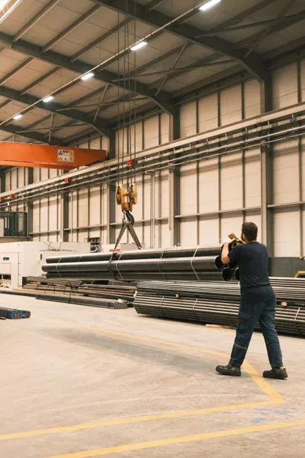
"Commissioning complete" is defined by a 72-hour continuous performance test under automatic control. Before the test starts, run the press through a minimum of three full consecutive cycles at design conditions to stabilise the cloth and confirm steady-state operation. Acceptance parameters are written into the contract: cake moisture content by sludge type (typical municipal biological sludge targets 65–75% moisture, industrial slurries vary widely), cycle time against design (commonly 30–90 minutes depending on cake thickness and feed concentration), filtrate clarity (turbidity typically < 100 NTU for municipal, lower for industrial), and solids capture rate (target > 95% for most applications).
During the 72-hour test, an operator log captures every trip, alarm, manual intervention, and process deviation. Any deviation outside the agreed tolerance is a punch-list item that must be resolved before final acceptance — the 72-hour clock is not paused for nuisance trips, and any intentional restart requires written acknowledgment from the client representative on site.
Documentation is the closing gate: as-built drawings reflecting any field changes, the O&M manual, the PLC program backup on a labelled USB or memory card, hydrostatic test and FAT certificates, calibration certificates for every instrument, and signed training records for the client's operators. Common handover gaps include the spare parts list (often shipped in a separate crate and missed), the lubrication schedule with grease type and interval for every bearing, and the first 30/60/90-day inspection plan that the client actually needs to follow. Closing these three items before the EPC leaves site is the difference between a handover that holds up at the 90-day mark and one that generates a callback.
Commissioning Failure Modes and Quick Fixes
Wet cakes and poor dryness trace to three root causes: feed concentration below the design window, insufficient pressure-hold time, or polymer dose wrong. The first is checked with a grab sample and a moisture analyser; the second by reviewing the cycle log against the design pressure-hold setpoint; the third by recalibrating the skid-mounted automatic polymer dosing skid against the current feed solids loading — polymer demand is non-linear with solids concentration, and a dosing skid commissioned on day one against one feed condition can be off by day 30 if the upstream process drifts.
Filtrate cloudy on day one almost always means cloth torn, cloth misaligned, or a plate seal channel. Re-fit the cloth on the suspect plate, re-check seam alignment, and inspect the seal groove for damage. Hydraulic cylinder drift points to internal seal wear, a pressure relief set too low, or a counterbalance valve failure on the hold circuit — verify the relief setpoint against the nameplate and check the counterbalance valve for debris before condemning the seals. Plate shifter faults are usually limit switch adjustment or low air pressure — the diagnostics are to bump the air supply to spec and re-stroke each switch.
PLC auto-cycle aborts require the operator to read the alarm log first and trace the trip to root cause. Bypassing a safety interlock to keep production running is a red line — every interlock exists because the failure mode it prevents has caused an injury or a major equipment loss on a similar installation. The fix is to clear the alarm, verify the field device, and restart the cycle, not to defeat the interlock. For broader context on dewatering technology selection, the filter press vs centrifuge comparison covers the operating-cost trade-offs that drive which unit is the right answer for a given sludge.
| Failure Mode | Likely Root Cause | First Check | Fix |
|---|---|---|---|
| Wet cake, high moisture | Low feed concentration, short hold time, wrong polymer dose | Feed solids grab sample, cycle log, dosing skid calibration | Adjust upstream thickening, extend hold setpoint, recalibrate dosing |
| Cloudy filtrate | Torn cloth, misaligned cloth, plate seal channel | Visual cloth inspection, seal groove check | Re-fit cloth, replace damaged plate seal |
| Hydraulic cylinder drift | Internal seal wear, low relief setpoint, counterbalance valve failure | Verify relief setpoint, check counterbalance for debris | Re-set relief, clean or replace counterbalance, re-seal cylinder |
| Plate shifter fault | Limit switch misadjustment, low air pressure | Air supply gauge, switch actuation test | Restore air to 0.6–0.8 MPa, re-stroke switches |
| PLC auto-cycle aborts | Safety interlock trip, field device fault | Read alarm log, identify first-out | Clear alarm, verify field device, restart — never bypass interlock |
| Long cycle time | Low feed pressure, cloth blinded, high cake thickness | Feed pump output, cloth condition | Restore feed pressure, wash or replace cloth, reduce cake thickness |
Frequently Asked Questions
How long does filter press installation and commissioning take on site? A 10-plate manual unit is typically 5–7 working days from truck arrival to handover. A 100-plate hydraulic unit with PLC control runs 3–5 weeks, and a 200+ plate fully automatic line can run 6–10 weeks. The largest schedule variable is civil readiness, not equipment delivery.
What pressure is used to test a filter press hydraulic system? The hydrostatic test is held at 1.25× the design working pressure for 30 minutes. For a typical 21 MPa working system, that is 26 MPa. The test gauge must be calibrated and the readings recorded at 0, 5, 10, 15, and 30 minutes for the test certificate.
Can a filter press be commissioned without running sludge through it? The mechanical, hydraulic, and PLC portions can be commissioned on water or a clean flush medium. The performance acceptance test, however, requires actual sludge at design conditions to verify cake moisture, cycle time, and filtrate clarity against the contract values.
What comes first — filter cloth fitting or hydraulic pressure testing? Hydraulic pressure testing comes first. Fitting cloths after the hydrostatic test risks tearing them on the first close. Cloths are installed after the pressure test passes but before the first production close.
Who signs off the performance acceptance test? The client representative, the EPC site manager, and the manufacturer's commissioning engineer all sign the test certificate. Any punch-list items must be closed within the contractually agreed window — typically 14 days — before final retention release.