Why Wastewater Plants Use Ultrasonic Level Sensors
An ultrasonic level sensor for wastewater treatment plant service is a non-contact transmitter that measures the distance from the transducer face to the liquid surface using a 20–200 kHz acoustic pulse, then outputs a 4–20 mA, HART, or RS-485 signal to the plant SCADA. The reason WWTPs reach for it first is simple economics: contact devices fail. Submersible hydrostatic probes foul with grease and rag; float switches snag on scum, and a single pump dry-run triggered by a stuck float typically costs 8–16 labor hours and a $1,500–$4,000 seal-and-impeller rebuild (per submersible pump service bulletins, 2025) — orders of magnitude more than the $50–$300 the sensor itself costs. Non-contact ultrasonic measurement removes the wetted sensor from the failure path entirely, which is why the NIVUS P-Series product copy describes the technology as "very low in maintenance through non-contact measurement" (NIVUS GmbH, DirectIndustry listing).
Default duty points for ultrasonic in a municipal or industrial WWTP include the inlet wet well, grit chamber, equalization basin, aeration tank, secondary clarifier, sludge hopper, and final effluent chamber. The rotary mechanical bar screen upstream of the wet well reduces but never eliminates rag, which is why the level sensor must keep its transducer face out of the liquid in the first place.
How an Ultrasonic Level Sensor Works in a WWTP
The operating principle is time-of-flight. The sensor emits an acoustic pulse, listens for the echo off the liquid surface, and divides the round-trip travel time by two. Sound speed in air at 20 °C is 343.2 m/s and changes by roughly 0.6 m/s per °C, so every commercial transmitter integrates a temperature sensor and applies compensation in firmware; a 10 °C swing without compensation will produce a 1.7% full-scale error. Wastewater air-space is acoustically hostile: relative humidity above an aeration basin routinely sits at 95–100%, with suspended water vapor droplets, H₂S, and surfactant foam all scattering or absorbing the beam at 20–200 kHz.
Two geometry terms decide whether the sensor survives a given wet well. The dead band (also called blanking zone) is the minimum distance — typically 0.07–0.3 m on commercial units — during which the receiver is blinded by the transmit pulse. Mounting the sensor any closer than the dead band to the high-level setpoint gives total signal loss. The beam angle defines the cone of acoustic energy; for an 80 kHz transducer it is roughly 8–12° at 1 m, widening at short range. The rule of thumb: the beam footprint at the liquid surface should land inside the tank footprint, and any ladder, inlet pipe, or wall within 1.5–2× the beam diameter will return a side-lobe echo that the firmware may misread as level. A stilling well or aiming bracket is therefore mandatory in narrow wet wells below about 1.5 m diameter.
Key Specifications for Wastewater Duty

The parameter table below is the artifact most engineers will print before a vendor meeting. It compares two reference units that bracket the WWTP duty envelope: a long-range hazardous-area unit (NIVUS P-Series) and a short-range chemically resistant unit (microsonic hps+). Both are real products with manufacturer-published specifications.
| Parameter | NIVUS P-Series | microsonic hps+ |
|---|---|---|
| Level range | 0.07–40 m | 0.03–8 m |
| Ingress protection | IP68 (1 m / 30 days) | IP67 |
| Process pressure | 5 bar (72.5 psi) | 6 bar (87.0 psi) |
| Process temperature | -30 °C to +95 °C | -25 °C to +70 °C |
| Transducer face / housing | PVDF (std), PTFE on request | PTFE membrane; PVDF or stainless housing; FFKM O-ring |
| Output signal | Analog (4–20 mA), HART, alarm relay | Analog, digital push-pull, IO-Link |
| Hazardous-area approval | ATEX Zone 0 and Zone 1 | None (industrial only) |
IP68 (submersible to 1 m for 30 days, per IEC 60529) matters in combined sewer systems, where wet-well flooding above the sensor during a 1-in-10 year storm event is a documented failure mode rather than a worst-case scenario. PTFE or PVDF transducer faces are specified over standard PVDF in digesters, chemical dosing sumps, and hypochlorite contact chambers because H₂S above 50 ppm and free chlorine above 5 ppm will pit unprotected faces inside 12–18 months. The microsonic hps+ uses an FFKM O-ring, which is rated for the same chemical envelope.
At the 2026 budget tier, 4–20 mA + HART + relay outputs are now standard on US$ 200–$299 ultrasonic transmitters (Made-in-China market data, 2026-01), so specifying a separate HART modem for SCADA integration is no longer necessary. For plants that already dose coagulant or polymer, an automatic chemical dosing system is a natural pairing — both subsystems share the same 4–20 mA loop-powered wiring standard.
Ultrasonic vs Radar vs Hydrostatic: Choosing the Right Technology
Most WWTP specification battles are decided at the technology gate, not the brand gate. The table below frames the decision for the five duty points a process engineer meets first.
| Criterion | Ultrasonic (20–200 kHz) | 80 GHz Radar | Hydrostatic probe |
|---|---|---|---|
| Clean water cost band (1 pc MOQ) | US$ 50–$299 | US$ 400–$1,200 | US$ 80–$400 |
| Foam performance | Poor (false echoes); use foam-suppression algorithm | Excellent (penetrates foam) | N/A (submerged) |
| Condensate / vapor performance | Poor to fair (absorbs pulse) | Excellent | N/A (submerged) |
| Narrow tank / stilling well | Good with stilling well | Excellent (small beam angle ~4°) | Not applicable |
| High-temperature digester | Limited (~+95 °C) | Excellent (up to +400 °C) | Limited by seal |
| Price multiplier vs ultrasonic | 1× (baseline) | 3–5× | 1–1.5× |
The rule of thumb: ultrasonic wins on price and is the default for clean effluent, inlet wet wells, and most equalization basins; 80 GHz radar wins wherever foam, condensate, or high temperature are structural rather than occasional, at a 3–5× hardware premium (Made-in-China and DirectIndustry market data, 2026-01); hydrostatic submersible probes are the fallback only when no usable air column exists — for example, raw sewage lift stations with confined access lids that block a 30° beam. Per duty point, the recommendation matrix is: inlet wet well → ultrasonic with IP68 (NIVUS P-Series is the reference benchmark); aeration basin with heavy foam → 80 GHz radar or ultrasonic with foam-suppression firmware; primary clarifier → ultrasonic with sun shield; digesters above 60 °C → 80 GHz radar; sludge hopper → ultrasonic with stilling well, or guided-wave radar if ragging is severe. A rotary mechanical bar screen ahead of the wet well reduces the rag load that would otherwise force a technology upgrade.
Installation and Wiring Best Practices
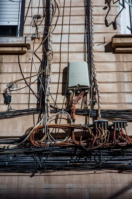
Mount the transducer so its face sits at least the published dead-band distance (0.07–0.3 m on most WWTP units) below the highest expected water level, and no further than 0.5× the maximum measurement range above the lowest level. Both numbers must be pulled from the chosen sensor's published spec sheet, not estimated. Maintain 1.5–2× the beam-diameter clearance between the beam axis and any wall, ladder, or inlet pipe — imagine a top-view cone opening downward from the sensor; nothing solid should intersect the cone between the transducer and the high-level setpoint.
Outdoor installations require a sun shield or weather hood above the transducer. Direct sunlight on a black PVDF housing creates a thermal boundary layer in the air column that refracts the acoustic beam downward and adds 2–5% level error on sunny afternoons — a real source of false high-level alarms in summer (HydropureWater field data, 2025-08).
For wiring, use a loop-powered 2-wire 4–20 mA connection for cost-sensitive wet wells, or a 4-wire configuration with dedicated HART or RS-485 to the SCADA RTU when multidrop polling is required. Match the loop power supply to the sensor's published minimum terminal voltage, typically 12–24 VDC at the sensor terminals after allowing for cable voltage drop. The PLC and RTU side of the wiring is covered separately in the SCADA system for industrial wastewater plant integration guide.
Troubleshooting the Three Common Failure Modes
Three failure modes drive roughly 90% of ultrasonic service calls in municipal and industrial WWTPs.
Symptom 1 — reading drifts high in cold weather. The integrated temperature sensor is blocked, shaded, or iced over, so the firmware is compensating against an artificially warm air column. Fix: verify the temperature sensor is exposed to free air, not trapped under insulation, debris, or a sun hood that holds daytime heat overnight.
Symptom 2 — reading locks at full range. Foam or condensation on the transducer face is absorbing the acoustic pulse before it leaves the housing. Fix: enable the foam-suppression algorithm (standard on most 2024-onward transmitters), install a small drip-clean nozzle fed with plant service water on a timer, or migrate the duty point to 80 GHz radar if the foam is structural rather than occasional. Condensate films of 0.1–0.3 mm are enough to absorb 50–80% of an 80 kHz pulse (microsonic application note).
Symptom 3 — erratic readings during pump cycling. Turbulence from the pump discharge is roughening the liquid surface and scattering the echo. Fix: enlarge the dead band by 20–30%, install a stilling well, or relocate the sensor to the stiller side of the basin, ideally opposite the pump inlet. Downstream of the wet well, a sludge dewatering filter press sees much steadier level conditions and is rarely a candidate for ultrasonic troubleshooting.
2026 Cost Band and Selection Checklist
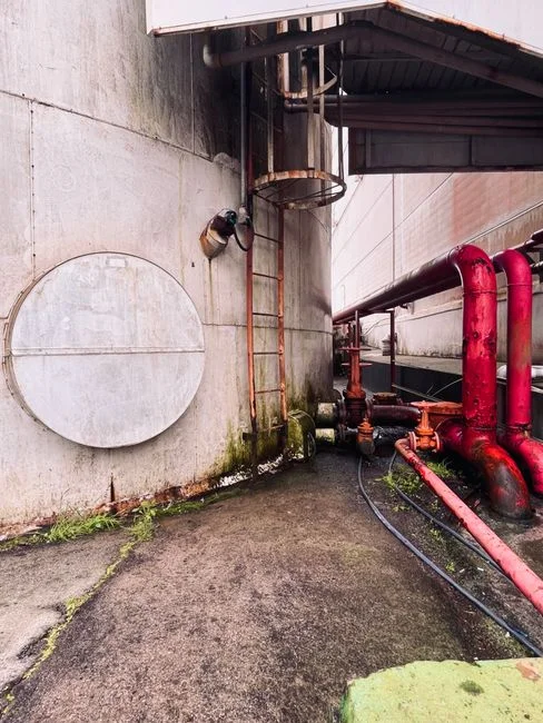
The 2026 hardware cost band for a WWTP-duty ultrasonic transmitter with 4–20 mA + RS-485 sits at US$ 50–$299 per unit at 1-piece MOQ (Made-in-China market data, 2026-01). Add a 30–50% premium for ATEX/IECEx-certified variants and another 20–30% for PTFE-face chemical-duty units. Installation — conduit, cable, sun shield, mounting bracket, and commissioning — typically adds 40–80% of hardware cost for a brownfield wet-well retrofit, dominated by confined-space entry labor and cable pulling rather than the sensor itself.
Final selection checklist before issuing a PO:
- Range — 0.07–40 m on the NIVUS P-Series, 0.03–8 m on microsonic hps+; match to the largest expected air gap with a 20% safety margin.
- IP rating — IP68 if the wet well can flood during a storm event; IP67 is acceptable in covered clarifier launders.
- Output protocol — 4–20 mA + HART is now table stakes at the $200 tier; specify RS-485 only if multidrop polling is required.
- Transducer material — PTFE face for H₂S, hypochlorite, or ferric chloride service; standard PVDF elsewhere.
- Approvals — ATEX Zone 0/1 mandatory for wet wells inside a classified digester gallery; otherwise non-classified units are acceptable.
- Total installed cost — not just the transmitter line item; the 40–80% installation adder is where the actual budget lives.
For plants standardizing on a packaged treatment line, the same selection logic carries into an integrated water purification system skid, where the level transmitter is one of several instruments sharing a common loop-power and SCADA interface.
Frequently Asked Questions
What is the typical measurement range of an ultrasonic level sensor for wastewater treatment plant duty? Commercial WWTP units span 0.07–40 m (NIVUS P-Series) on the long end down to 0.03–8 m (microsonic hps+) on the chemically resistant short end. Select a sensor whose maximum range is at least 20% greater than the largest expected air gap at the mounting point.
How does an ultrasonic sensor differ from an 80 GHz radar sensor in foam? 80 GHz radar penetrates foam with negligible signal loss because the wavelength (~4 mm) is smaller than the foam bubble structure, while 20–200 kHz ultrasonic pulses are absorbed and scattered by the same foam — see the technology comparison above.
What is the dead band on an ultrasonic level transmitter? The dead band (blanking zone) is the minimum distance — typically 0.07–0.3 m — where the receiver is blinded by the transmit pulse. The transducer face must be mounted at least this far from the highest expected water level or the unit will return total signal loss.
Can an ultrasonic sensor survive being submerged in a flooded wet well? Yes, if rated IP68 (submersible to 1 m for 30 days per IEC 60529), as the NIVUS P-Series is. IP67 units tolerate temporary splash but not continuous submersion, and will fail within hours in a flooded chamber.