Separate the data center's wastewater streams
A Bloemfontein data center needs separate treatment strategies for sanitary sewage and industrial process wastewater: cooling tower blowdown typically dominates the process stream because evaporation leaves dissolved minerals, solids and cooling chemicals behind. The engineering task is to classify every stream, measure blowdown chemistry and temperature, identify the receiving authority’s discharge conditions, and match pretreatment, reverse osmosis scaling control and reuse to the selected endpoint. Sanitary sewage and process wastewater should not share a design assumption simply because both eventually require water management.
Sanitary sewage comes from staff toilets, kitchens and washrooms. Cooling tower blowdown is removed to control accumulation of dissolved salts, corrosion products, microbiological growth and scale in the circulating cooling water. Other sources include softener backwash, equipment-cleaning wastewater, RO reject and air-handling condensate. Each stream has a different flow, chemistry, destination and permit pathway.
RSP Engineers identifies cooling tower blowdown as the primary process-wastewater source in most large-scale data centers and notes that its volume is typically minor compared with potential blowdown flow (RSP Engineers, undated). Its data center cooling blowdown treatment guide provides a useful starting point, but its U.S. permit references must not be transferred directly to Bloemfontein.
The key blowdown parameters are temperature, pH, TDS or conductivity, silica, calcium and hardness, chlorides, sulfates, phosphates, residual biocides, corrosion inhibitors, and metals such as copper and zinc. RSP Engineers gives a pH range of 6.0–9.0 and a maximum temperature example of 150°F only as examples for a project-specific discharge application; neither is a universal South African limit. The project engineer must obtain Bloemfontein’s applicable conditions directly from the municipality, sewer authority and relevant environmental regulator.
Establish the treatment objective before selecting equipment
Equipment selection should follow the required endpoint, not precede it. Direct sewer discharge, surface-water discharge, on-site reuse and zero-liquid-discharge concepts impose different treatment, permitting, utilities and residual-management requirements. Black & Veatch frames the alternatives analysis around four project-specific questions: can blowdown enter the receiving body directly, can the local wastewater plant accept it without additional treatment, is on-site treatment required, and does the interceptor have enough capacity (Black & Veatch, undated).
For Bloemfontein, the owner should compare each route against receiving-water capacity, sewer acceptance, treatment complexity, freshwater reduction and residual disposal. The data center cooling blowdown treatment guide should be read as a technical reference, not as evidence that the same U.S. discharge route applies locally.
Cooling make-up reuse requires more than generic potability. The recovered stream must meet the chemistry needed by the cooling system, including its treatment chemicals and operating concentration. Dust control or construction reuse has a different quality specification. Where cooling design remains open, the University of Georgia Extension reports that closed-loop systems can reduce water consumption by up to 70% compared with traditional open evaporative cooling, although they require more electrical power and greater system complexity (University of Georgia Extension, 2026).
| Treatment objective | Primary engineering question | Indicative process scope | Key unresolved input |
|---|---|---|---|
| Municipal sewer discharge | Will the sewer authority accept the stream and at what quality? | Characterisation, equalisation, pH control and treatment required by the authority | Local acceptance conditions, connection capacity and analytical methods |
| Surface-water discharge | Which receiving body and authorisations apply? | Quality treatment, temperature control and receiving-water assessment | Applicable South African environmental authorisation and site-specific limits |
| Cooling make-up reuse | Can the recovered water meet cooling-system chemistry requirements? | Industrial wastewater pretreatment and reverse osmosis scaling control | Feed chemistry, cycles of concentration, recovery target and reuse demand |
| Non-cooling reuse | What quality and quantity are required? | Treatment matched to the intended end use | End-use specification and user acceptance criteria |
| Zero liquid discharge | Can all concentrate and solids be managed on site? | Maximum recovery plus crystallisation or other residual treatment | Residual chemistry, disposal route, energy demand and maintenance capability |
Characterize the blowdown and confirm the receiving authority's limits

Measured blowdown chemistry is the boundary condition for pretreatment, reverse osmosis scaling control, residual generation and permit design. Characterisation should cover source-water chemistry, the complete cooling chemical package, seasonal operating conditions, blowdown cycles of concentration, temperature and the maximum and average discharge flows. Sampling should include periods that expose the effect of chemical dosing, clean-outs, high evaporation and upset operation.
Request laboratory analysis for pH, TDS or conductivity, suspended solids, silica, calcium, total hardness, chlorides, sulfates, phosphate, residual biocides, corrosion inhibitors, and metals such as copper and zinc. Certified laboratories should use methods agreed with the receiving authority. The sampling plan should also identify the data needed for equipment guarantees: feed-water envelope, recovery definition, permeate quality, concentrate quality and chemical consumption.
The municipality, sewer authority and relevant environmental regulator should confirm the connection route, prohibited discharges, temperature and pH controls, monitoring duties, reporting, sampling points, analytical methods and treatment requirements. Do not assume that the U.S. Clean Water Act, NPDES or a state pretreatment programme applies in South Africa. The applicable South African and municipal requirements must be identified through direct regulator consultation and documented in the project’s compliance register.
| Information package | Required content | Use in engineering design |
|---|---|---|
| Representative sampling plan | Locations, operating conditions, sampling frequency, flow measurements and laboratory methods | Defines design-basis chemistry and peak loading |
| Source and cooling-system data | Make-up-water analysis, chemical inventory, cycles of concentration, control settings and clean-out practices | Links blowdown generation to treatment demand |
| Authority correspondence | Acceptance conditions, prohibited discharges, monitoring, reporting and connection requirements | Creates the compliance and controls basis |
| Operational monitoring plan | Recurring samples, certified analysis, pH and flow monitoring where required, and upset response | Supports commissioning and ongoing compliance |
RSP Engineers describes ongoing sampling, certified laboratory analysis, reporting, and potentially continuous pH and flow monitoring as part of discharge compliance (RSP Engineers, undated). An industrial wastewater pretreatment reference can help structure the sampling-to-treatment logic, but its stated regulatory scope should not be assumed to govern this project.
Build the pretreatment and treatment process train
A defensible process train starts with equalisation and solids removal where required, then controls pH and removes selected contaminants before the water reaches the endpoint-specific treatment stage. Equalisation protects downstream equipment from variable flow and chemistry; filtration protects membranes and reuse systems. Chemical precipitation is justified where measured metals require it. Disinfection belongs only where the selected reuse or discharge objective needs it.
For suspended solids, oil and grease, FOG and colloidal material, dissolved air flotation can be considered. DAF selection for suspended solids and FOG should be tied to the waste stream and required separation performance. A DAF removes floatable or suspended material; it does not remove dissolved salt and therefore does not solve reverse osmosis scaling by itself.
Ultrafiltration can protect an RO train by removing bacteria, colloids and suspended solids without chemical addition. The ultrafiltration pretreatment for RO has a catalog range of 2,000–40,000 L/h, 0.03-micron PVDF membranes, turbidity up to 300 ppm, automatic backwash and air scour. These are equipment specifications, not a Bloemfontein design flow or feed-water guarantee.
Industrial RO is the principal desalinating step where high-quality cooling make-up is required. The industrial RO system for blowdown reuse has a stated recovery capability of up to 95%. IDE Tech reports that conventional brackish-water RO commonly reaches 75–80% recovery before scaling becomes unmanageable (IDE Tech, 2026). Actual recovery depends on feed chemistry, cycles of concentration, membrane configuration, scaling control and operating discipline.
An advanced high-recovery route combines conservative local RO with controlled precipitation of silica, calcium carbonate and other scaling salts as dense solids. IDE Tech reports a case operating at around 95% recovery with permeate silica of about 1 mg/L (IDE Tech, 2026). This is a reported application result, not a guaranteed outcome for a Bloemfontein facility.
| Process step | Function | Design input | Principal residual or control issue |
|---|---|---|---|
| Equalisation and solids removal | Stabilise flow and remove material that may foul equipment | Peak flow, suspended solids, oil and FOG, operating variability | Sludge or float characterisation and removal route |
| pH adjustment and selected precipitation | Protect downstream assets and remove regulated metals where necessary | Measured pH, metals and authority conditions | Chemical consumption and metal-bearing solids |
| Filtration and UF | Remove suspended material and protect RO | Feed-water envelope, turbidity and flow profile | Retentate stream, backwash controls and membrane cleaning |
| RO | Remove dissolved salts for high-quality reuse | TDS, silica, hardness, temperature, recovery and permeate quality | Concentrate, membrane scaling and cleaning demand |
| Disinfection | Control microbiological risk where required | Reuse destination and authority requirement | Residual chemical and dosing control |
| Residual management | Contain and dispose of concentrate or solids lawfully | Residual chemistry, quantity and receiving facility | Transport, storage and permit obligations |
Compare the main equipment routes
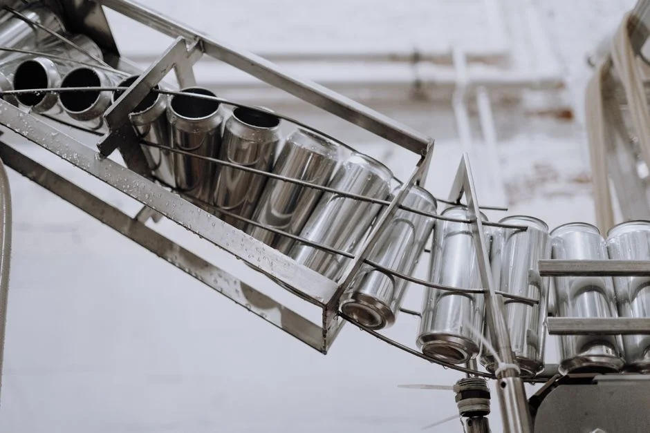
The equipment decision should follow a traceable chain from measured chemistry to required endpoint. A discharge-focused route may need pH adjustment and filtration; a reuse route adds scalable pretreatment and RO; a high-recovery route adds controlled precipitation and residual management. No route should include every unit merely because it appears in a catalogue.
The procurement inputs are measured design flow, blowdown cycles of concentration, TDS, silica, hardness, biocide and inhibitor package, required reuse quality, available footprint, electrical power, chemical storage, drainage, maintenance access and the residual-disposal route. The DAF and clarifier comparison is useful when solids removal remains unresolved, but the data center’s actual stream must drive the decision.
| Equipment route | Best suited when | Main advantages | Principal risks or constraints |
|---|---|---|---|
| pH adjustment and filtration | Authority conditions can be met with limited contaminant removal | Lower process complexity | Temperature, solids, metals and biocide limits may remain untreated |
| Advanced pretreatment with metal removal | Measured metals or solids require dedicated removal | Protects discharge route and downstream equipment | Chemical dosing and metal-bearing solids |
| RO-based reuse | Cooling make-up requires lower dissolved salts | Supports freshwater reduction and water reuse | Silica and other scaling salts, concentrate disposal and energy demand |
| High-recovery precipitation plus RO | Water recovery is prioritised and residual treatment is feasible | Separates sparingly soluble salts from the remaining brine | More complex control, solids handling and site services |
Two catalogue statements require discipline. The stated RO recovery of up to 95% is a product capability, not a project guarantee; the UF flow range of 2,000–40,000 L/h describes available equipment, not the required data-center capacity. Final sizing must use measured average and peak flows. Chemical dosing, storage, containment, controls, alarms and duty/standby strategy must be included in the auxiliary scope even where not offered by the main equipment supplier.
Plan reuse, residuals and site infrastructure
Reuse begins with a defined demand and quality specification. Confirm whether recovered water will feed cooling make-up, dust suppression, construction reuse, landscape irrigation or another approved purpose, then identify who will operate and accept the stream. Cooling make-up recovery may reduce potable demand and blowdown volume, but the cooling system’s chemistry package and cycles of concentration determine the required treatment and whether recovered water can be accepted without adverse scaling or corrosion.
Reserve space for equalisation and storage tanks, pumps, RO skid controls, chemical storage with appropriate containment, drainage, vehicle access, sampling points, laboratory requirements and maintenance clearances. RSP Engineers reports that a simple pH-neutralisation system may occupy a few hundred square feet, while filtration and chemical precipitation may require several thousand square feet (RSP Engineers, undated). These are comparative footprint examples, not a Bloemfontein sizing allowance.
Every RO concentrate and chemical-precipitation solid needs a documented route. Confirm the receiving facility’s acceptance criteria, transport requirements, storage containment and applicable authorisation before treating the residual as a disposal solution. The automatic chemical dosing system should be specified around measured chemical demand, containment, duty, fail-safe response and remote monitoring rather than a generic pumping arrangement.
Operational monitoring should include flow, pH, temperature and conductivity, with additional analytes defined by the discharge or reuse specification. Define what happens when a limit is exceeded: isolate the affected route, divert to an approved holding state, notify operations and perform confirmatory sampling. This closes the loop between equipment, laboratory evidence and permit compliance.
Use a staged implementation and procurement plan
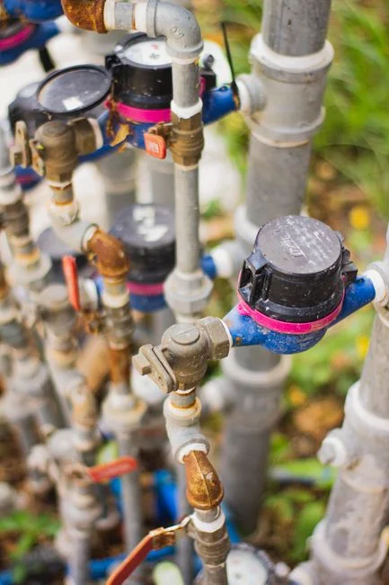
A staged sequence reduces redesign risk: source characterisation, utility and regulator consultation, alternatives analysis, pilot testing where chemistry or scaling remains uncertain, detailed design, equipment procurement, commissioning and compliance verification. Pilot work should test the proposed process against representative blowdown rather than source-water samples that omit cooling chemicals and concentration effects.
Request suppliers to state guaranteed feed-water envelopes, permeate and concentrate quality, the recovery calculation boundary, availability, chemical consumption, redundancy, controls scope, installation requirements, residuals and acceptance-test criteria. “Up to” recovery without an accompanying feed-water envelope does not establish project performance.
The industrial water balance should distinguish gross cooling-water demand, evaporation, blowdown, recovered reuse, potable make-up and final discharge. IDE Tech cites up to 2 million litres per day for a 100-megawatt facility as an upper-demand example (IDE Tech, 2026). It is not a Bloemfontein sizing input: the project engineer needs the local cooling configuration, meteorological design basis, operating profile and measured flow data.
Civil and utility coordination should start before equipment orders are placed. Confirm drainage routes, residual loading, chemical delivery access, power, control-network architecture, isolation and maintenance clearances. The industrial wastewater reuse strategy offers a reuse-planning reference, but its jurisdiction and November 2026 publication date should not be treated as a Bloemfontein regulatory source.
- Complete the source-water, blowdown and residual characterisation.
- Obtain written authority and utility position on the discharge or connection route.
- Develop the industrial water balance and compare reuse, discharge and hybrid alternatives.
- Pilot uncertain pretreatment or scaling-control steps.
- Freeze the treatment train, site-services interface and performance guarantees.
- Procure, commission, sample and demonstrate compliance before normal operation.
Frequently Asked Questions
Can a data center discharge cooling blowdown into Bloemfontein’s municipal sewer?
Possibly, but only after the municipality or sewer authority confirms that the specific stream is acceptable, identifies the applicable connection or industrial-user conditions, and confirms treatment, monitoring and analytical requirements. Do not route blowdown to a stormwater system. Sanitary sewage, cooling blowdown, softener backwash, equipment-cleaning wastewater, RO reject and condensate should remain separately characterised even if they eventually share a nominated connection point.
How should treatment equipment be sized?
Use representative average and peak flows, measured feed chemistry, cooling cycles of concentration, the required recovery or reuse quality and the authority’s discharge conditions. UF and RO catalogue flow ranges are screening references, not design values. Pilot testing is justified where silica, hardness, biocide chemistry or scaling behaviour remains uncertain, because small water-balance errors can change both membrane loading and concentrate volume.
What should a buyer include in the treatment-cost and budget request?
Ask for a priced scope separated into equipment, pretreatment, chemical dosing, membranes, tanks and pumps, controls, utilities, installation, commissioning, monitoring, operator training, maintenance and residual handling. The principal cost drivers are flow and chemistry, recovery target, pretreatment complexity, chemical use, energy, concentrate or sludge removal, laboratory testing and site infrastructure. No defensible price can be given without local flow, chemistry, reuse demand, residual route and utility requirements.
How should suppliers be compared before selecting an RO or pretreatment package?
Compare suppliers against the same written performance basis. Require guaranteed feed-water envelopes, permeate and concentrate quality, recovery definition, chemical consumption, redundancy, controls and alarms, installation constraints, residual outputs, commissioning tests, acceptance criteria and local compliance support. Then verify whether the proposed treatment train matches the site’s measured chemistry and authority requirements. The industrial RO system for blowdown reuse should therefore be evaluated as one component of a complete, guaranteed process—not as a standalone capacity promise.