How Semiconductor Wastewater Changes the Equipment Choice
In 2026, Largo semiconductor factories should generally choose DAF when wastewater contains floatable oils, surfactants, colloids, or floc-prone solids and rapid solids capture in a compact footprint is important. A conventional or lamella clarifier is usually more suitable when the solids are reliably settleable, flow is comparatively stable, and simpler operation is preferred. Neither device independently removes dissolved semiconductor chemicals such as TMAH, DMSO, MEA, or chelating agents. Final selection should follow representative stream sampling, jar testing, and pilot validation using the required downstream treatment endpoint.
That decision must be made drain by drain, not from one bulk sample. Analog fabrication and DLP fabrication drains can differ in composition, temperature, pH, chemical inventory, and batch timing. Treating them as a single uniform wastewater stream creates a poor basis for separator sizing and chemical selection.
Separate three treatment questions: what can float, what can settle, and what remains dissolved. The first two belong to solids separation. The third may require biological treatment, membrane treatment, or other advanced treatment after the solids are removed. A semiconductor DAF and clarifier selection guide provides the broader decision framework.
The dissolved load deserves particular attention. Science.gov’s 2008 LCD wastewater research identified DMSO, MEA, TMAH, and chelating agents as important TFT-LCD components and reported that organic solvents accounted for more than 33% of total TFT-LCD wastewater. That optoelectronic evidence is not a universal semiconductor design basis, but it demonstrates why a solids-only equipment decision is inadequate. An industrial DAF system for semiconductor wastewater pretreatment should therefore be evaluated as part of a complete treatment train.
Build the Factory Stream Map Before Comparing Equipment
A defensible separator selection begins with a verified stream inventory, because a bulk flow average can hide short chemical dumps and changing solid behavior. Every drain needs a source owner, flow record, batch profile, chemical inventory, and segregation decision.
| Information to obtain | Why it affects selection |
|---|---|
| Flow, batch duration, pH, temperature, and conductivity | Defines hydraulic loading, chemical demand, corrosion exposure, controls, and equalization needs. |
| TSS, settleable fraction, floatable fraction, particle distribution, and colloid behavior | Shows whether gravity separation is credible and whether DAF or chemical conditioning can improve capture. |
| Oil and grease, surfactant species, foam observations, and emulsion characteristics | Identifies floatable loads, foaming risk, skimming demand, and downstream interference. |
| TMAH, DMSO, MEA, chelating agents, and other process compounds | Establishes dissolved-treatment duties and chemical-compatibility requirements. |
| Compatibility of caustics, solvents, surfactants, cleaning chemicals, and temperature changes | Sets requirements for seals, piping, float collection, coagulants, and flocculants. |
Representative sampling must span production and batch states rather than only steady operation. Low turbidity cannot prove that a stream is easy to treat: chemically destabilized colloids, emulsions, or precipitated contaminants may remain nearly invisible while generating substantial sludge.
Request compatibility information from every prospective supplier, including the proposed automatic chemical dosing package. Chemical selection and metering cannot be separated from the separator because inconsistent conditioning can defeat either flotation or settling.
DAF Performance in a Semiconductor Treatment Train
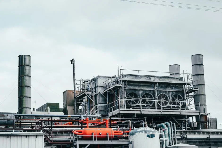
DAF is a front-end separator for material that can be floated, conditioned into floatable floc, or captured with attached bubbles. The normal treatment sequence is equalization, chemical conditioning where required, saturation or air induction, bubble-particle contact, flotation, skimming, and transfer of clarified water.
Clearwater Industries describes the separation mechanism as 30–50 micron microbubbles attaching to impurities and flocculated particles. The resulting floating sludge blanket is removed by a skimmer. The same source states that heavier solids can settle into a bottom collection zone and require separate removal, so flotation does not eliminate settled-solids handling.
Two flotation design references from the supplied research are useful for framing vendor proposals: bubble-floc rise rates of 4–12 gpm/ft² and standard forward-flow air saturation of 15%–30%. These are design references from Reynolds & Bauhm, not universal semiconductor guarantees. The same research gives a typically optimized contact angle of 40–80 degrees, but surfactants can change particle surface behavior and bubble attachment; the applicable condition must be established for the actual stream.
Principal DAF risks are foaming, fragile floc, recycle-system or air-system limitations, float carryover, and misplaced expectations about dissolved-solids removal. The micro-bubble flotation design criteria and engineering checklist for selecting DAF equipment are useful for building that test scope.
DAF is often appropriate before biological treatment, UF, or RO when oils, surfactants, floatables, or colloids could foul or interfere with the next stage. It protects downstream equipment; it does not remove the dissolved semiconductor compounds that those stages may need to address.
When Lamella Clarification Is the Better Fit
Gravity clarification is the stronger candidate when the main solids load is dense, reliably settleable, and comparatively stable. It is also attractive where basin space is available and avoiding compressed-air and recycle-pump systems simplifies operation.
A lamella clarifier adds inclined settling surfaces, increasing available clarification area within a defined footprint. It does not remove hydraulic-loading, solids-loading, or sludge-withdrawal constraints. Equalization, conditioning where needed, settling, sludge collection, and clarified-water withdrawal remain part of the process.
HydropureWater’s manufacturer information for a lamella clarifier for settleable semiconductor wastewater solids states surface-loading rates of 20–40 m/h and chemical-consumption reduction of up to 30%. Those are manufacturer claims, not independently established semiconductor performance values. The chemical benefit depends on the actual wastewater and operating basis.
The decision should be tested against poor settling, hydraulic overload, insufficient footprint, and the chemical and sludge-handling consequences of failure. Gravity clarification also does not remove dissolved organics or dissolved metals; additional biological treatment or polishing may still be required. Low apparent turbidity should not be accepted as proof that no conditioning is needed.
Compare Procurement and Operating Consequences
DAF and clarification should be compared as operating systems, not as tank quotations. The separator, conditioning, sludge removal, controls, utilities, and downstream consequences determine the commercial result.
| Procurement criterion | DAF | Conventional or lamella clarification |
|---|---|---|
| Target material | Floatable oils, surfactants, conditioned colloids, and suitable floc-prone solids | Dense, reliably settleable solids |
| Footprint | Generally compact because separation rates are higher, subject to equipment design | Generally requires more clarification area and basin space |
| Hydraulic sensitivity | Recycle, bubble generation, contact-zone performance, and skimming must remain stable | Distribution, settling, and sludge withdrawal become critical |
| Conditioning | May be required to enlarge floc and improve bubble attachment | May be required where particles do not settle naturally |
| Utilities | Continuous recycle-pump and compressed-air demand | Fewer powered separation components; chemical pumps and sludge withdrawal remain |
| Controls and maintenance | Requires attention to pumps, compressor, saturation system, nozzles, and float mechanism | Requires attention to scrapers, sludge collection, settling zone, and basin condition |
| Sludge | Float may contain oil, surfactants, and conditioned solids | Settled sludge behavior depends on solids and conditioning |
| Downstream use | Useful before biological treatment, UF, or RO where floatables could interfere | Useful before biological treatment or membranes where settleable solids are the main burden |
Neither sludge stream should be assumed to be easiest to dewater. Float and settled sludge can differ in solids concentration, free oil, surfactants, and water content. Before specifying a filter press for the separated solids, obtain representative sludge samples and test the complete dewatering train.
Include the automatic chemical dosing system for the separator package, because dosing quality can determine process success. Request project-specific comparisons for utilities, chemical quotations, sludge volume, operator labor, maintenance, and downstream impacts. The supplied research does not support a universal energy, chemical, removal, or cost figure.
Select Through Jar Tests and Pilot Validation
Equipment selection should progress from representative sampling to jar testing, pilot validation, and only then a performance-guaranteed proposal. Each stage resolves a different procurement risk.
| Validation stage | Required evidence | Decision enabled |
|---|---|---|
| Stream characterization | Flow and mass-loading records, solids fractions, particle behavior, oils, surfactants, dissolved chemicals, pH, temperature, and conductivity | Identify credible separation mechanisms and drainage boundaries. |
| Jar tests | Conditioning, settle or float behavior, solids capture, chemical demand, foaming, and sludge observations | Eliminate unsuitable mechanisms and establish preliminary chemical and control requirements. |
| Pilot testing | Representative removal behavior, hydraulic response, controls, foaming, scaling, and sludge data | Confirm performance under relevant production variability. |
| Final proposal | Design flow, solids-loading basis, chemical assumptions, utilities, performance basis, controls, startup, operator intervention, support, and guarantees | Compare commercial scope and allocate remaining risk. |
DAF pilots should examine recycle rate, air saturation, bubble-particle attachment, contact-zone performance, and skimming under batch variability. Clarification pilots should examine settleable-solids loading, hydraulic distribution, sludge withdrawal, and overflow stability.
The selected separator should be evaluated as front-end protection for biological treatment, membranes, polishing, discharge, or reuse. It is not the final destination for dissolved contaminants, and its guarantee should not imply otherwise.
Verify Materials, Controls, Downstream Treatment, and Guarantees
Material selection must follow the complete chemical and temperature envelope of the selected drains. SigmaDAF USA states that its standard DAF clarifiers are manufactured in 304SS, with 316SS, polypropylene, and other materials available upon request. That is a procurement reference, not confirmation that any listed material suits every semiconductor wastewater condition.
Require the proposal to state utility assumptions for recycle flow, compressed air, power, controls, sensors, chemical storage, washdown, and maintenance access. Also establish whether chemical dosing, sludge handling, biological treatment, UF, RO, ozone, controls, and site utilities are inside or outside the supplier’s quoted scope.
Downstream equipment must be evaluated by function. UF for colloid and suspended-solids control does not replace biological removal of dissolved semiconductor compounds. An industrial RO system for wastewater reuse should be assessed against the required reuse endpoint, concentrate handling, pretreatment, and operating controls—not permeate values alone. Where biological treatment is planned, the MBR wastewater treatment system becomes a separate performance obligation.
Study results provide context, not transferable guarantees. The cited LCD MBR/RO research reported average COD removal above 97.3%, TOC removal of 97.8%, and BOD5 removal of 99.4%. A separate MBR/RO/ozone study reported average COD removal above 98.5% and TOC removal of 97.4%. These results belong to the cited TFT-LCD studies and cannot be applied to another factory without matching wastewater and operating conditions.
Require treatment guarantees to define the tested stream, design flow, solids-loading basis, chemical assumptions, utility availability, performance endpoint, measurement method, and exclusions. A separator guarantee should not imply that dissolved contaminants have been removed.
Frequently Asked Questions
Which equipment is cheaper for a Largo semiconductor factory: DAF or a clarifier?
The supplied research does not support a universal cost figure. Compare stream-specific utility tariffs, chemical quotations, sludge-disposal routes, footprints, maintenance scope, operator labor, and downstream effects. Require the comparison to use the same design basis and treatment endpoint.
How should a semiconductor factory size a DAF or lamella clarifier?
Size from design flow, solids-loading basis,
Frequently Asked Questions
Is DAF or a clarifier cheaper for a semiconductor wastewater treatment system?
In terms of initial capital expenditure (CAPEX), lamella clarifiers generally offer a lower entry cost due to their simple, gravity-based design with fewer moving parts. Dissolved Air Flotation (DAF) systems require additional mechanical components such as air saturation pumps, compressors, and recycle systems, which typically increase the initial equipment cost by 20% to 40% compared to equivalent clarifiers.
However, operational expenditure (OPEX) analysis often favors DAF when processing low-density semiconductor waste streams, such as light chemical mechanical planarization (CMP) slurries, due to higher sludge solids content (often 3% to 5% vs. 1% to 2% for clarifiers). This reduces downstream sludge dewatering costs, potentially offsetting the higher CAPEX over a 3- to 5-year lifecycle in high-flow semiconductor facilities.
How do you size a DAF or lamella clarifier for semiconductor factory wastewater?
For lamella clarifiers, sizing is governed by the projected surface overflow rate (SOR), typically ranging from 0.5 to 1.5 m/h for semiconductor effluent to ensure effective settling of fine silica particles. The total required clarifier area is calculated by dividing the peak flow rate by the SOR, then applying a safety factor of 1.2 to 1.5 to account for variable influent loading and chemical dosing fluctuations.
DAF sizing is determined by the hydraulic loading rate and the air-to-solids (A/S) ratio. For CMP wastewater, the A/S ratio is typically maintained between 0.01 and 0.05 ml of air per mg of suspended solids. The hydraulic loading rate for DAF units in this sector is generally higher than clarifiers, often ranging from 4 to 10 m/h, which allows for a significantly smaller physical footprint in space-constrained fab environments.
What performance guarantees should I request from a semiconductor wastewater equipment supplier?
You should mandate performance guarantees based on specific effluent quality targets, including Total Suspended Solids (TSS) removal efficiency of at least 95% and a maximum outlet turbidity of less than 10 NTU. It is essential to define these guarantees against specific influent parameters, such as a maximum CMP particle concentration of 500–1,000 mg/L, to ensure the equipment is not over-promised for extreme spike conditions.
Additionally, request guarantees regarding chemical consumption rates, such as kilograms of coagulant and flocculant required per cubic meter of treated water. Suppliers should also provide warranties on mechanical reliability, such as a minimum 98% uptime guarantee, and specific guarantees on the dryness of the resulting sludge cake if the unit is integrated with a sludge removal system.
Can DAF or a clarifier alone make semiconductor wastewater compliant?
No, neither DAF nor clarification is sufficient as a standalone process for semiconductor wastewater to meet typical discharge or reuse standards. These technologies primarily address physical separation of suspended solids and colloidal matter, but they do not remove dissolved pollutants such as fluorides, heavy metals (copper, nickel), or complex organic compounds commonly found in fab effluent.
Compliance usually requires a multi-stage process where DAF or clarification acts as a pretreatment step. Without subsequent chemical precipitation, advanced oxidation, or membrane filtration, the effluent will likely fail to meet stringent local environmental regulations regarding dissolved ionic contaminants and chemical oxygen demand (COD) levels.
What treatment should follow DAF or clarification in a semiconductor wastewater train?
Following primary solids removal, the process train should incorporate chemical precipitation and pH adjustment to address dissolved heavy metals and fluorides, often utilizing lime or calcium chloride dosing. This is typically followed by secondary clarification or multi-media filtration to remove any precipitated solids or residual flocs that passed through the primary stage.
For high-purity discharge or water reclamation goals, the tertiary stage should include membrane processes such as Ultrafiltration (UF) for final particulate removal, followed by Reverse Osmosis (RO) to manage total dissolved solids (TDS) and ionic contaminants. In cases of high organic loading, an Ion Exchange (IX) or Granular Activated Carbon (GAC) unit may also be required to reach specific sub-ppm compliance levels for trace contaminants.