What Micro Bubble Flotation Is and Why the Design Criteria Matter
Microbubble flotation is a dissolved air flotation (DAF) regime in which the rising-gas phase is dominated by bubbles in the tens of micrometers, produced by pressurizing a clarified recycle stream and releasing it through a nozzle or needle-valve manifold into the contact zone of the flotation tank. The SUEZ Water Handbook frames the physics with a single comparison: one 2 mm diameter bubble requires the same air volume as 1,000,000 bubbles of 20 µm diameter, and bubbles of millimetric size create turbulence that "jeopardises the satisfactory combination of 'white' water with the flocculated water" (suezwaterhandbook.com, Microbubble Flotation DAF or FAD).
The design criteria are the engineering levers used to push the unit onto the fine-bubble side of that trade-off: microbubble diameter, saturation pressure, recycle ratio, air-to-solids (A/S) ratio, hydraulic loading rate, and reactor geometry. Industrial plants in 2026 face tighter FOG, TSS, and COD pre-treatment limits, and the same SUEZ reference notes that the A/S ratio is the single biggest determinant of the downward separation velocity a unit can sustain at a given hydraulic loading. A microbubble DAF is a defined operating regime with measurable bubble-size, pressure, and geometry inputs. This guide consolidates the numeric values from the cited research into a parameter table and translates them into the questions an engineer should put to a supplier before issuing an RFQ. For a working specification of a packaged DAF skid that already covers the flow range discussed here, see this HydropureWater DAF system overview.
Consolidated Micro Bubble Flotation Design Parameters
A parameter table serves as the primary artifact for sizing a unit and incorporating data into a design basis. The table below uses values that appear in the cited research; rows where the source did not publish a specific number are flagged so the engineer knows to request that value from the OEM against the specific TSS/FOG load.
| Design parameter | Value / range | Source | Notes |
|---|---|---|---|
| Microbubble diameter target | ~67% of bubbles < 20 µm (TCRI-A generator, 0.9 MPa) | Liu et al., Sep. Purif. Technol., 2010 | Specify bubble-diameter distribution at operating pressure, not nominal pore size |
| Saturation pressure | 0.9 MPa (bubble-generation study) | Liu et al., Sep. Purif. Technol., 2010 | Higher pressure raises dissolved-air mass; verify pump head against saturation-tank pressure drop |
| Reactor height-to-diameter ratio (H/D) | 10, 20, 30 tested; gradual performance gain as H/D rises | Koirala, UNBC MSc thesis, 2024-02 | Specify the H/D of the proposed unit; generic datasheets typically do not disclose this |
| Saturation-tank dissolution efficiency | > 90% achievable with packing | SUEZ Water Handbook | Packing NOT recommended — fouling risk and premature pressure release produce large bubbles in the contact zone |
| Mass-transfer coefficient KLa (microbubbles) | 1.1754 min-1 vs 0.7535 min-1 conventional | Liu et al., Sep. Purif. Technol., 2010 | Faster OTR supports a lower coagulant dose |
| Hydraulic loading rate | Not published as a single value in cited research | — | Request site-specific value from OEM against the TSS/FOG load |
| Air-to-solids (A/S) ratio | Not published as a single value in cited research | — | Per SUEZ, drives the achievable downward separation velocity — request match to suspended-solids or FOG mass load |
| Recycle ratio | Not published as a single value in cited research | — | Request value matched to saturation pressure and target A/S |
Two design exclusions require attention in the table footnotes. The SUEZ Water Handbook explicitly recommends against packing saturation tanks despite their higher dissolution efficiency, because head loss in the pressurized distribution circuit triggers premature pressure release and large-bubble formation in the contact zone. Additionally, electroflotation is rarely used, and any OEM claim built around it should be treated as a non-standard bid.
Reactor Geometry: Height-to-Diameter Ratio as a Design Variable

The Koirala MSc thesis (UNBC, 2024-02) provides the only cited research that systematically varies reactor geometry: three configurations at H/D = 10, 20, and 30 were tested, demonstrating that "reactor configuration slightly affected system performance, with gradual improvement observed as the height-to-diameter ratio increased" (UNBC, 2024). A taller reactor provides bubbles more rise time and allows the floc–bubble aggregate more retention in the separation zone, raising effective removal without changing the air system. This gain is incremental, so H/D should be optimized against civil cost and plant footprint. Ask the OEM for the H/D of the proposed reactor and the pilot-versus-full-scale performance data behind that geometry. If the answer is a single black-box footprint number with no H/D disclosure, treat the bid as a conventional DAF and adjust the expected removal figures accordingly. Where a specific industrial duty is being specified, the geometry discussion in a related DAF design guide for confectionery wastewater walks through similar trade-offs on a high-FOG feed.
Performance Benchmarks from Bench and Pilot Studies
Published headline figures allow engineers to populate design documents with citable, verified data. The table below pulls the published figures together so the engineer can copy them into a specification document with the inline attribution intact.
| Study / scale | Feed / conditions | Result | Source |
|---|---|---|---|
| Bench optimum (oil/water) | Initial oil 1995 mg/L; 45 min gravity settling + 38 min flotation | 98.8% oil/water separation (R² = 0.99, adj R² = 0.98) | Koirala, UNBC MSc thesis, 2024-02 |
| Pilot scale (75 L) | Oily wastewater, 1 hour | 92% oil removal vs 4.62% for gravity separation alone; ~100% when NB/MB flotation combined with adsorption | Koirala, UNBC MSc thesis, 2024-02 |
| Lab comparison (dyeing wastewater) | Same conditions, PAC coagulant | COD removal +30%, color removal +110%, oil removal +40% vs conventional air-bubble flotation; BOD/COD from 0.290 to 0.363 (vs 0.301 conventional) | Liu et al., Sep. Purif. Technol., 2010 |
| Mass-transfer comparison | Dyeing wastewater, same reactor | KLa 1.1754 min-1 (microbubbles) vs 0.7535 min-1 (conventional) | Liu et al., Sep. Purif. Technol., 2010 |
| Mobile WTTP (homogenized clay) | 200 mg/L alum coagulant, 200 L/h, steady state | 98% turbidity removal end-to-end | Joni et al., J. Phys. Conf. Ser. 2344, 2022 |
These figures represent bench and pilot numbers, providing evidence for what a microbubble DAF can deliver on industrial-strength feeds. For an industrial plant comparing this technology against a clarifier retrofit, the broader DAF vs clarifier decision guide for food and beverage plants translates similar removal numbers into a flow-and-load comparison.
Air-to-Solids, Recycle Ratio, and the Saturation System
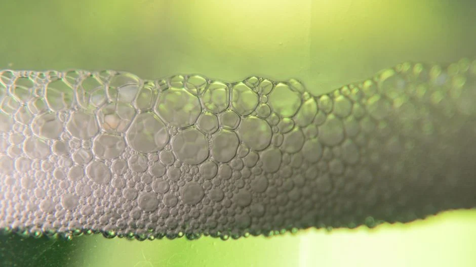
The A/S ratio and the recycle ratio define whether a DAF unit will meet its removal guarantee. The SUEZ Water Handbook states the governing relationship directly: "the greater this ratio, the greater the rising force imparted to the particles and the faster the downward velocity can become" (suezwaterhandbook.com, Microbubble Flotation DAF or FAD). The cited research did not publish a single canonical A/S or recycle value, which is why the parameter table above flags those rows for OEM confirmation against site-specific TSS or FOG loads. Regarding the saturation tank, packed tanks can reach > 90% dissolution efficiency but are not recommended because fouling and head loss in the pressurized distribution circuit trigger premature pressure release and large-bubble formation in the contact zone. The practical implication is that an OEM specifying a packed saturation tank is offering a feature that the SUEZ reference actively advises against. For a worked example of how A/S and recycle interact with a high-strength protein feed, the DAF design for gelatin wastewater article walks through these variables on a specific industrial duty.
From Design Criteria to Equipment Selection: What to Ask the OEM
Design criteria are only useful when translated into specific procurement questions. The table below maps each criterion to a verifiable supplier deliverable and the application evidence that demonstrates the OEM can deliver on it.
| Design criterion | Question to put to the OEM | Acceptable evidence |
|---|---|---|
| Bubble-diameter distribution | What fraction of bubbles is < 20 µm at the rated operating pressure? | Measured distribution at 0.9 MPa class pressure (Liu et al. reports ~67% < 20 µm) |
| Saturation-tank design | Is the saturation tank packed or unpacked? What is the dissolution efficiency? | Unpacked design; efficiency stated; SUEZ note on packing risk acknowledged |
| Reactor H/D | What is the proposed H/D, and what pilot or full-scale data supports it? | H/D disclosed; performance data referenced (UNBC tested H/D 10, 20, 30) |
| Hydraulic loading rate | What is the rated hydraulic loading for my TSS and FOG load? | Site-specific calculation provided against the feed |
| A/S and recycle ratio | What A/S and recycle ratio are you guaranteeing for my solids load? | Both values stated and tied to the saturation pressure |
| Materials and skimmer | What materials of construction and what skimmer type? | Compatible with feed chemistry; automatic skimming stated |
The HydropureWater DAF range covers 4–300 m³/h across 13 standard models, uses micro-bubble technology with automatic skimming, and is referenced against food processing, pulp & paper, textile, metalworking, petrochemical, and municipal pre-treatment applications (hydropurewater.com product catalog). Most industrial DAF retrofits rely on hydraulic matching to the upstream coagulation–flocculation step; the Liu et al. (2010) result that microbubble flotation significantly reduced coagulant dose only yields real savings if the upstream coagulant dose window is verified against the new unit. When the feed is novel, pilot testing is the safest path; the Koirala (UNBC, 2024) progression from bench optimum at 1995 mg/L initial oil to a 75 L pilot at 92% removal in one hour is the scale-up workflow to expect before a full-scale order is placed.
Frequently Asked Questions
How do I size a microbubble DAF for a given flow and TSS load?
Size on three inputs: hydraulic loading rate, A/S ratio, and recycle ratio. The OEM should be asked to match all three to the site-specific solids or FOG mass load, with the saturation pressure stated explicitly. Cross-check the proposed H/D against the UNBC 2024 result that performance improves gradually as H/D rises from 10 to 30.
What should I check when comparing DAF suppliers in 2026?
Ask for the bubble-diameter distribution measured at the rated operating pressure, the proposed reactor H/D with supporting pilot data, a pilot run on a feed similar to yours, the skimmer design, the materials of construction, and confirmation that the unit integrates with the existing coagulation–flocculation step.
Frequently Asked Questions
What are the design criteria for a micro bubble flotation (DAF) system?
The primary design criteria for a modern DAF system involve the air-to-solids (A/S) ratio, hydraulic loading rate, and rise rate. For industrial applications, an A/S ratio between 0.01 and 0.05 ml air/mg solids is typically required to ensure effective particle attachment. Hydraulic loading rates generally range from 5 to 15 m³/m²/h, depending on the specific gravity of the influent particles and the target removal efficiency.
What microbubble diameter and saturation pressure should I specify for industrial DAF?
To maximize collision efficiency with suspended solids, specify a microbubble diameter range of 10 to 100 micrometers. Achieving this bubble distribution requires a saturation pressure between 400 and 600 kPa (approx. 60–90 psi) within the saturation tank. Operating outside these ranges often results in either insufficient buoyancy or excessive turbulence, both of which degrade effluent quality.
How do I choose between DAF suppliers for an industrial wastewater plant in 2026?
Selection should be based on the supplier's ability to provide digital twin modeling and real-time sensor integration compatible with 2026 Industry 4.0 standards. Prioritize manufacturers that offer verified pilot test data for your specific waste stream and provide automated chemical dosing control loops that adjust coagulant/flocculant consumption based on real-time influent turbidity and zeta potential measurements.
What flow range and lead time should I expect for a packaged industrial microbubble DAF?
Packaged DAF units are typically available in flow ranges from 5 m³/h to 250 m³/h per skid. As of 2026, standard lead times for modular, factory-tested units range from 12 to 20 weeks. Extended lead times may apply for custom metallurgy requirements, such as 316L stainless steel or specialized internal coatings required for high-salinity or highly corrosive industrial effluents.
Can microbubble flotation meet 2026 industrial pre-treatment limits for FOG, TSS, and COD?
Yes, microbubble flotation is highly effective for meeting stringent 2026 discharge standards. When optimized, these systems can achieve FOG removal efficiencies exceeding 95-98%, TSS reduction of 85-95%, and particulate COD removal of 60-80%. Performance is contingent upon correct pre-flocculation chemistry and maintaining a stable bubble-to-particle contact zone within the flotation tank.