How a Sedimentation Tank Actually Works
A sedimentation tank is a gravity-based vessel that removes suspended solids from wastewater by letting heavier particles settle and lighter scum float. Settling efficiency depends on particle size, density, water temperature, turbulence, flow stability, bottom-cleaning frequency, and flocculation (Siberian Academic Book LLC, S1). In a horizontal flow settling tank, influent is distributed evenly across the cross-section at the inlet so that a stable, low-turbulence zone lets suspended solids fall to the bottom or float to the surface. Where higher concentrations of undissolved particles are present, particles grow by agglomeration — a process the engineer can promote with agitation, coagulant dosing, or biological agents, and which defines flocculent settling as opposed to discrete-particle settling (S1).
To anchor the design target, S1 walks through a 2 m × 20 m × 45 m horizontal tank at 0.5 m³/s and 10 °C. The Reynolds number for the bulk flow exceeds 2000 — turbulent, but acceptable — and the Camp number lands on the order of 1×10⁻⁵, which means short-circuiting is not expected. With a 3600 s residence time at 2 m depth, the integrated suspended-solids profile shows more than 80% of settleable solids removed (S1). That is the realistic ceiling for a single, well-designed horizontal unit. The catch is that downstream trains can still fail to reach permit: a Fenton oxidation–neutralization–coagulation–sedimentation train on secondary clarifier effluent delivered 73.4% CODCr removal (Journal of Environment and Earth Science, 2019-07) — useful, but the work confirms a clarifier is one unit operation in a chain, not a stand-alone discharge.
The Physics That Sets Tank Size: Stokes, Reynolds, and Overflow Rate
For a discrete spherical particle, terminal settling velocity comes from balancing gravity against fluid drag. In drinking-water practice, settling is usually laminar and Stokes' law applies, with the drag coefficient C_D = 24/Re. The Stokes relation is the working equation engineers cite on drawings because most primary clarifier particles fall inside the laminar envelope. The Reynolds number for the settling particle is defined using the particle diameter, terminal velocity, and the kinematic viscosity of water — and that last variable is the bridge to water temperature. Kinematic viscosity falls as temperature rises, so the same particle settles faster in summer than in winter, which is why a cold-weather design margin matters (S1).
Regime boundaries matter for the same reason. S1 puts laminar settling at Re < 1, transition between 1 and 1600, and fully turbulent above 1600 — meaning a designer cannot lean on Stokes when particles are large or densities are high. Translating particle physics to tank geometry gives the overflow rate, also called surface loading rate: a particle settles out only if its terminal velocity v_s exceeds v = Q / A, where Q is the flow rate and A is the tank surface area. For rectangular continuous-flow service, King County caps the overflow rate at 1.0 gpm/ft² (King County, S4). When suspended-solids concentrations rise, particles no longer settle as discrete grains — they agglomerate into larger flocs whose effective diameter grows, so the engineer can deliberately stage flocculation upstream of the clarifier to lift v_s (S1).
| Parameter | Definition / formula | Source value or regime | Source |
|---|---|---|---|
| Stokes settling velocity | v_s = (g·d²·(ρ_p − ρ_w)) / (18·μ) | Valid for laminar settling, Re < 1 | S1 |
| Particle Reynolds regime — laminar | Re < 1 | Drinking-water practice usually laminar | S1 |
| Particle Reynolds regime — transition | 1 < Re < 1600 | Drag coefficient not constant | S1 |
| Particle Reynolds regime — turbulent | Re > 1600 | Drag coefficient flattens | S1 |
| Overflow rate (surface loading) | v = Q / A | Maximum 1.0 gpm/ft² for rectangular continuous flow | S4 |
| Kinematic viscosity of water | μ = f(T) | Falls as temperature rises; raises v_s | S1 |
Sedimentation Tank Types: Horizontal, Circular, and Lamella
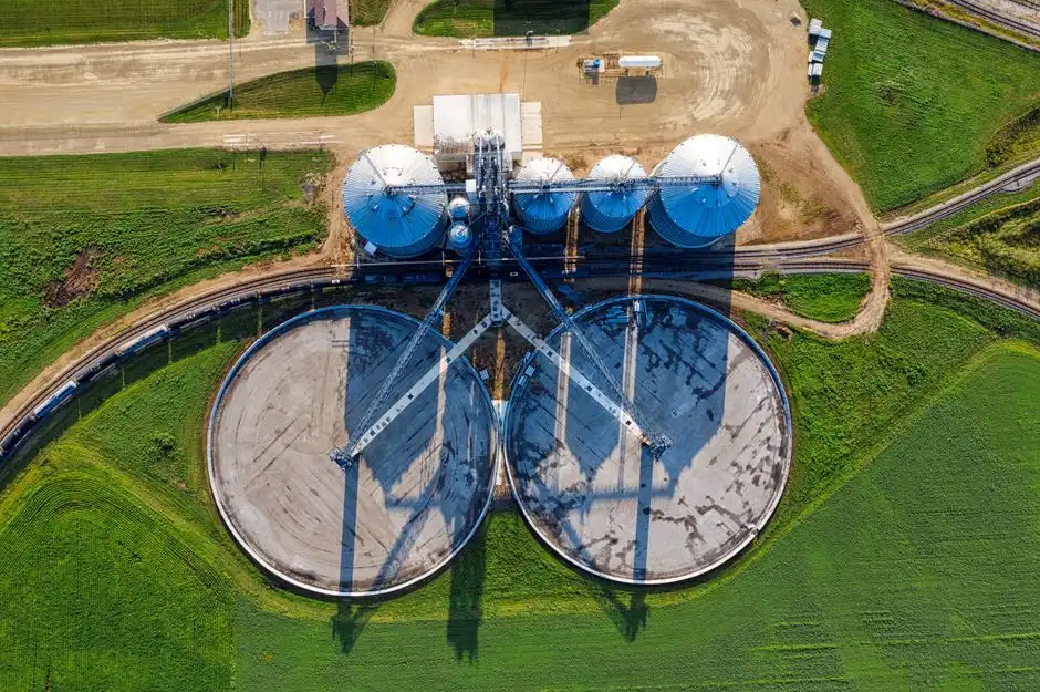
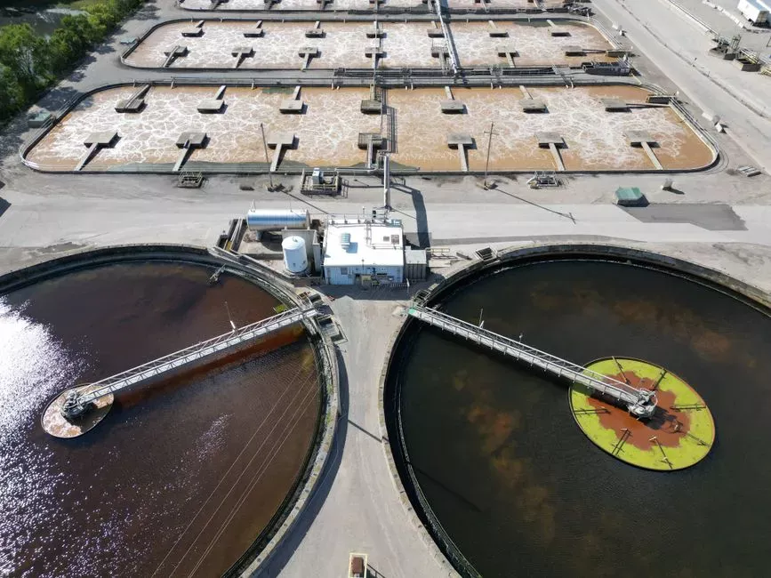
Three configurations dominate 2026 procurement: horizontal flow, circular scraper-fed primary clarifier, and lamella (inclined-plate) settler. The S1 2 m × 20 m × 45 m geometry is the canonical horizontal reference; the cawd.org reference plant (S3) defines the canonical circular geometry at 60 ft diameter with 9 ft side water depth, mechanical scrapers on a sloping bottom, scum skimmers into collecting hoppers, and double-sided circumferential launders spilling into junction boxes. Rectangular continuous units are flow-through and simple to build, but they require a length-to-width ratio of at least 4:1 to limit short-circuiting — a King County mandate (S4) echoed in the design commentary at waterandwastewater.com (S5). Circular batch units suit intermittent or construction-site flows, with a minimum 60-min quiescent settling time, a maximum 25% sediment accumulation, and a 7 mL/L settleable-solids cap in the discharge (S4).
Lamella clarifiers change the geometry problem. By stacking inclined plates, the effective settling area A in the overflow-rate equation grows without growing the tank footprint, so surface loading rates climb to 20–40 m/h — and the HydropureWater high-efficiency lamella sedimentation tank quotes up to 30% lower chemical consumption by recycling sludge into the flocculation zone. Removal benchmarks from the same source set: rectangular units typically remove 50–70% of suspended solids and 25–40% of BOD (S5), while the cawd.org circular primaries remove about 60–65% of suspended solids (S3). The decision is footprint, peak flow, and chemical-handling tolerance — not just removal percentage.
| Configuration | Reference geometry | Typical removal | Key regulatory or design constraint | Source |
|---|---|---|---|---|
| Horizontal flow | 2 m × 20 m × 45 m, 0.5 m³/s, 10 °C | ≥ 80% settleable-solids removal at 3600 s residence, 2 m depth | Check Reynolds & Camp numbers for short-circuiting | S1 |
| Circular primary clarifier | 60 ft diameter, 9 ft SWD, mechanical scraper, double-sided launders | 60–65% suspended solids | Sludge & scum piped to anaerobic digestion | S3 |
| Rectangular continuous | ≥ 4:1 length-to-width | 50–70% TSS, 25–40% BOD | Overflow rate ≤ 1.0 gpm/ft²; HRT ≥ 90 min | S4, S5 |
| Circular batch | Site-specific | Discharge settleable solids ≤ 7 mL/L | 60 min quiescent; ≤ 25% sediment accumulation | S4 |
| Lamella / inclined-plate | Stacked plates inside compact shell | Footprint-driven; chemical use up to 30% lower | Surface loading 20–40 m/h | S6 |
Sizing and Design Equations You Will Actually Use
The sizing path for a 2026 spec follows five steps, and each step has a number an engineer can hand to a supplier.
- Set HRT. 90 minutes minimum for rectangular continuous flow under peak instantaneous conditions; 60 minutes quiescent for circular batch (S4).
- Compute volume. V = Q_peak × HRT, where Q_peak is the lower of the tank's max discharge rate or the local sewer utility's max discharge rate. If Q_peak exceeds one tank's capacity, add parallel units (S4).
- Check overflow rate. Divide instantaneous flow (gpm) by surface area (ft²); cap at 1.0 gpm/ft² for rectangular continuous units (S4).
- Fix geometry. Enforce a length-to-width ratio of at least 4:1 on rectangular tanks; verify Reynolds and Camp numbers against the S1 worked example to control short-circuiting risk.
- Control sludge. Limit sediment accumulation to ≤ 25% of working volume, measured as an average of three equally spaced sections in a rectangular tank (S4).
The catch on the secondary side is real. If the best the downstream train can manage is 73.4% CODCr removal (S2), the primary must be either over-sized or chemically aided — coagulant or flocculant dosing, or a lamella geometry that lifts surface loading and protects the biology from solids overload. Where downstream sludge handling is the bottleneck, pair the clarifier with a dewatering unit sized to the expected solids yield; for a packaged skid approach, a mechanical screening engineering guide upstream and a downstream filter press downstream keeps the train coherent. For flows where flotation beats gravity — high oil or emulsified load — a DAF vs clarifier selection guide is the right next read.
2026 Selection Checklist for B2B Buyers
Use this as a defensible RFQ checklist. Every line ties to a measurable acceptance value the supplier has to answer, not a marketing claim.
| RFQ criterion | Acceptance value the supplier must quote | Source |
|---|---|---|
| Hydraulic retention time at peak instantaneous flow | ≥ 90 min rectangular continuous; ≥ 60 min circular batch quiescent | S4 |
| Overflow rate (surface loading) | ≤ 1.0 gpm/ft² rectangular; 20–40 m/h for lamella | S4, S6 |
| Geometry constraint | ≥ 4:1 length-to-width rectangular; ≥ 60 ft diameter justification for circular primaries | S3, S4, S5 |
| Removal guarantee at design flow | 50–70% TSS and 25–40% BOD (rectangular); 60–65% SS (circular primary) | S3, S5 |
| Sludge & scum handling | Scraper mechanism, sludge sump, scum hopper, downstream dewatering capacity (e.g. HydropureWater plate and frame filter press) | S3, S6 |
| Chemical strategy | If footprint-tight: lamella with up to 30% lower coagulant/flocculant use; dosing via HydropureWater automatic chemical dosing system | S6 |
| Compliance envelope | Discharge settleable solids ≤ 7 mL/L; ≤ 25% sediment accumulation; document local sewer utility's peak cap | S4 |
| Automation | PLC-controlled sludge withdrawal, scum pumps, integrated packaged option (e.g. HydropureWater JY series integrated coagulation–sedimentation–filtration unit) | S6 |
For high-color or high-emulsion streams, the trade is between a clarifier and a DAF — the DAF vs clarifier for textile wastewater guide gives the matching decision logic. Where space is constrained, the lamella option collapses the same acceptance values into a smaller envelope at the cost of plate inspection access.
Frequently Asked Questions
What is a sedimentation tank and what does it actually remove?
A sedimentation tank is a gravity-based vessel that lets settleable and floatable matter separate from wastewater. The horizontal reference geometry in the Siberian Academic Book LLC study (2 m × 20 m × 45 m, 0.5 m³/s, 10 °C) delivered more than 80% settleable-solids removal at 3600 s residence (S1). In a real rectangular service tank, expect 50–70% TSS removal and 25–40% BOD removal (S5); circular primary clarifiers typically remove 60–65% of suspended solids (S3).
How do I size a sedimentation tank for a 2026 project?
Compute volume from V = Q_peak × HRT with HRT ≥ 90 min for rectangular continuous units and ≥ 60 min quiescent for circular batch (S4). Then check the overflow rate Q/A against 1.0 gpm/ft² for rectangular units (S4), enforce a 4:1 length-to-width ratio, and verify Reynolds and Camp numbers against the S1 worked example to control short-circuiting.
What does a sedimentation tank cost, and what should I budget for?
The supplied research does not quote a unit price, so a budget number cannot be defended from the evidence. Ask each supplier for an itemized quote that includes the tank shell, scraper mechanism, sludge and scum pumps, the PLC package, and the downstream dewatering unit (for example, a plate and frame filter press). Required buyer inputs are peak instantaneous flow (gpm or m³/s), influent TSS, target effluent TSS, footprint constraint, and local sewer utility's peak discharge cap (S4).
How do I choose between a conventional clarifier and a lamella unit?
Use a conventional rectangular or circular clarifier when footprint is not binding and chemical handling is straightforward — the cawd.org reference plant removes 60–65% of suspended solids in a 60 ft diameter primary (S3), and rectangular units remove 50–70% of TSS (S5). Specify a lamella clarifier when footprint is tight or TSS load is high: a HydropureWater high-efficiency lamella sedimentation tank reaches 20–40 m/h surface loading and reduces coagulant and flocculant consumption by up to 30% (S6). The supplier selection question to put on the RFQ is which option meets your stated overflow rate, surface loading rate, HRT, removal target, and chemical budget — and whether the proposal includes an integrated coagulation–sedimentation–filtration skid (such as the JY series) to control interface risk between unit operations.