
What a Primary Sedimentation Tank Does in an Industrial Treatment Train
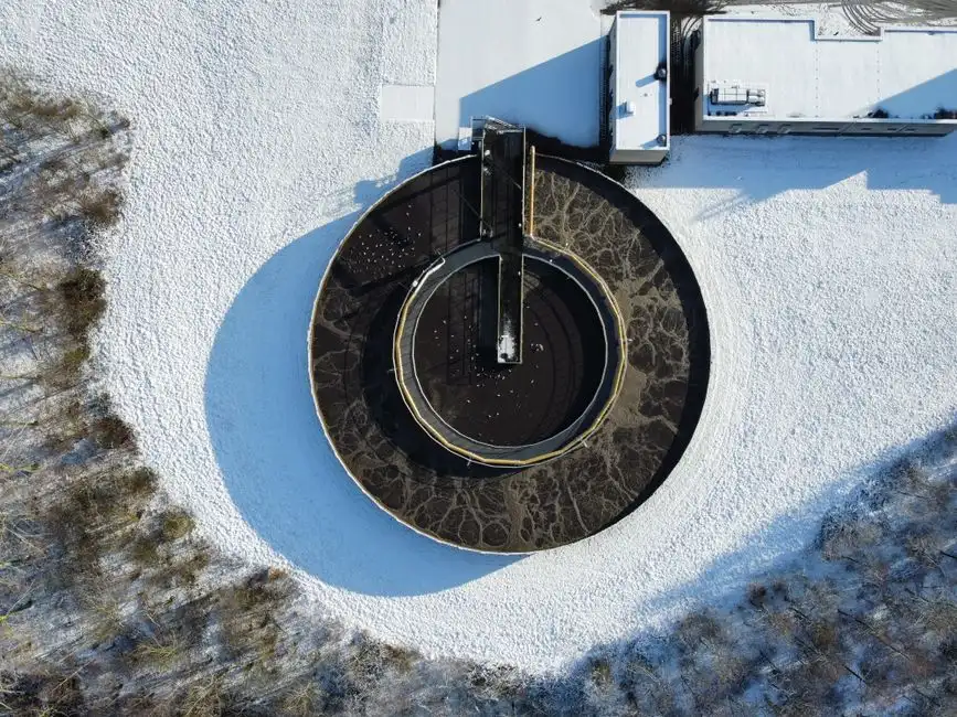
A primary sedimentation tank is a gravity-driven clarifier positioned between preliminary screening and biological treatment in a conventional wastewater train. Its job is straightforward: slow the influent down so that settleable suspended solids drop to the floor as primary sludge while oils and greases rise to the surface as scum, letting clarified supernatant move on to secondary or biological stages (S3, waterandwastewater.com, primary sedimentation article).
The primary tank is not a polishing step. It does not target dissolved organics, ammonia, or colloidal material that escapes gravity settling. Its role is load reduction: cutting the BOD and TSS that hit the biological stage so that aeration basins, MBRs, or trickling filters can run at design loading without being over-fed (S3). In that sense, primary sedimentation is a sizing lever for everything downstream — if the primary step is undersized or poorly configured, no amount of aeration tank volume will compensate.
The same unit operation is used in both municipal and industrial plants, although industrial sites typically have to handle higher and more variable influent solids, more oil and grease, and tighter effluent constraints (S3). Primary sedimentation is also a meaningful capital item: per the model and pilot work discussed in S2 (Water, MDPI, doi 10.3390/w9060448), primary settling accounts for an important share of the capital cost of a conventional plant that includes both primary and secondary stages. That cost weight is one reason the choice between a conventional tank and a compact lamella design has real procurement consequences, not just a footprint one.
How Settling Actually Works: From Stokes to Modern Design
Primary sedimentation design rests on a body of settling theory that goes back more than 170 years. Stokes, in 1851, formulated the equation describing the settling velocity of spherical discrete particles under quiescent laminar flow conditions — the textbook baseline still used to bound particle behaviour in clarifiers (S2). For real wastewater, the picture is more complex: Kynch, in 1952, proposed a kinetic theory of sedimentation based on concentration changes, valid for ideal suspensions but not appropriate for flocculent suspensions that form compressible sediments (S2).
In primary settling tanks (PSTs), discrete settling conditions can be assumed for relatively low inlet concentrations, which is the typical operating case (S2). At higher solids loadings, particles flocculate as they settle, the suspension becomes compressible, and the simple Stokes picture no longer holds. A 1970s line of work attempted to unify dispersed and flocculating suspension theory, but in practice, real PST design still leans on empirical performance relationships built from pilot and full-scale data (S2).
More recent work has layered computational fluid dynamics (CFD) on top of the classical theory. CFD models are now used to predict flow patterns and suspended solid distributions inside sedimentation tanks, including the effect of baffle configuration and baffle angle on performance (S2). Multiple experiments are still required to obtain solid-removal contour plots at different heights and times and to construct charts describing the total solid-removal percentage at a given time (S2). The practical takeaway for a 2026 buyer: theory sets the boundary conditions and helps interpret CFD, but the design you sign a PO on is still anchored in empirical relationships — surface overflow rate, HRT, and pilot-validated removal curves — not in first-principles calculation alone.
Design Parameters That Actually Govern Performance
The single most important design ratio for a primary sedimentation tank is the surface overflow rate, also called surface hydraulic load, defined as q = Q/A, where Q is the flowrate (m³/s) and A is the surface area (m²) of the sedimentation basin (S2). Everything else — depth, weir length, baffling — is downstream of getting q right, because q directly determines the settling velocity a particle needs to beat in order to be removed.
Hydraulic retention time (HRT) is the second governing parameter. Typical primary sedimentation HRT values range from 1.5 to 3 hours, providing adequate settling time without excessive tank volume or energy use (S3, waterandwastewater.com). Pushing HRT beyond 3 hours buys very little additional removal and inflates civil cost; cutting it below 1.5 hours sharply raises the risk of solids carryover. HRT and q are linked but not interchangeable — a deep narrow tank and a shallow wide tank at the same q will have different HRTs, and that difference matters for flocculent suspensions where contact time drives floc growth.
The pilot data behind most modern primary tank design was generated on semi-technical installations operated over four months at three decreasing surface hydraulic loads: 1.4, 1.0, and 0.8 m³/m²·h, with the lower values chosen to obtain relatively high removal efficiencies (S2, Water, MDPI, doi 10.3390/w9060448). That 0.8–1.4 m³/m²·h band is the conventional performance envelope a vendor should be able to point to.
Temperature is a real design input, not a footnote. Per Metcalf & Eddy as cited in S2, in cold climates the increased viscosity of water slows the sedimentation rate, which establishes a direct relation between temperature and the required hydraulic retention time. A plant designed for a 20 °C summer feed cannot be assumed to perform identically at 5 °C without an HRT adjustment. Effective sedimentation also depends on minimising turbulence within the tank: excessive turbulence can resuspend settled particles and cut removal efficiency (S3).
| Parameter | Symbol / unit | Typical range for conventional PST | Source |
|---|---|---|---|
| Surface overflow rate (hydraulic load) | q = Q/A, m³/m²·h | 0.8–1.4 (pilot range); lower values for higher removal | S2 |
| Hydraulic retention time | HRT, h | 1.5–3 | S3 |
| Temperature effect on viscosity | — | Cold influent → increase HRT per Metcalf & Eddy | S2 |
| Turbulence control | — | Minimise; resuspension erodes removal | S3 |
Tank Geometry: Rectangular, Circular, and the Lamella Alternative
Conventional primary sedimentation tanks are commonly classified by shape: rectangular or circular, with each configuration tuned to specific hydraulic and site conditions (S3, waterandwastewater.com). Rectangular tanks are typically used where long, narrow footprints are available and flow distribution is fed from one end; circular tanks (centre-feed or peripheral-feed) are common where compact radial footprints fit a site better. Both rely on the same surface overflow rate envelope — the 0.8–1.4 m³/m²·h pilot range from S2 is the conventional baseline either way.
The third path is a lamella or inclined-plate settler. Rather than relying on a deep quiescent zone, a lamella design uses a stack of inclined plates to reduce the effective settling distance a particle must fall before it hits a surface. The published product data for the HydropureWater high-efficiency lamella sedimentation tank quotes surface loading rates of 20–40 m/h, an order of magnitude above the conventional band, by combining sludge recirculation, flocculation, and inclined-plate separation in a single compact structure. The same source claims chemical consumption reductions of up to 30% versus a conventional coagulation–sedimentation setup because the recirculated sludge acts as a floc weight.
That figure should be read as vendor-claimed performance from the S6 product catalog, not as a third-party validated number. A 2026 buyer evaluating the conventional-versus-lamella decision should anchor the comparison on the same three parameters: surface overflow rate, HRT (or equivalent plate residence time), and footprint. Conventional rectangular/circular tanks make sense where footprint is cheap, influent is steady, and chemical cost is a minor operating line. A lamella design is worth specifying where footprint is constrained, peak-to-average flow ratios are high, or coagulant/flocculant cost is a significant operating expense. The 20–40 m/h surface loading figure (S6) is the engineering argument; whether it converts to a real-world removal and OPEX win on a specific feed is something the supplier has to demonstrate with pilot or reference-plant data on a comparable wastewater.
| Configuration | Typical surface loading | Footprint | Flow variability tolerance | Source |
|---|---|---|---|---|
| Conventional rectangular PST | 0.8–1.4 m³/m²·h | Large | Moderate | S2, S3 |
| Conventional circular PST | 0.8–1.4 m³/m²·h | Large | Moderate | S2, S3 |
| Lamella / inclined-plate settler | 20–40 m/h (vendor claim) | Compact | Higher, with sludge recycle | S6 (HydropureWater catalog) |
Expected Removal: BOD, TSS, and What Comes Off the Bottom
Primary sedimentation performance is typically evaluated by reductions in BOD and TSS (S3, waterandwastewater.com). The exact removal percentage is a function of the influent characteristics — settleable fraction, particle size distribution, temperature — and the tank design parameters discussed above, so a single universal number is misleading. What can be said with confidence is that these reductions significantly lower the treatment burden on secondary and tertiary processes (S3), which is the core economic argument for getting the primary step right rather than relying on downstream biology to absorb the load.
As a downstream benchmark rather than a primary tank result, the Fenton oxidation–neutralization–coagulation sequence applied to a secondary clarifier feed reached 73.4% CODCr removal in the work reported in S1 (IISTE, 2019). That figure is useful only as a reference point for what a tertiary chemistry step can add after a well-run primary stage; it is not a primary tank performance number and should not be quoted as one.
The other output stream is primary sludge. Primary sludge handling is itself regulated and typically involves thickening, digestion, dewatering, and controlled disposal or energy recovery (S3). On an industrial site, that means the plate and frame filter press for primary sludge dewatering is part of the same procurement conversation as the primary tank itself, because sludge yield, solids concentration, and dewatering behaviour all feed back into tank sizing and sludge storage volume.
Sizing a Primary Tank in 2026: Inputs to Give Your Supplier
A vendor cannot quote a real primary sedimentation tank without a defined set of inputs. Drawing on the design factors in S2 and S3, the minimum information a 2026 industrial buyer should be ready to provide is: design flow (average and peak), influent suspended solids and BOD concentrations, target hydraulic retention time, target surface overflow rate, available site footprint, and the expected influent temperature range. Without these, any quotation is a placeholder, not a design.
Two specific asks tighten the conversation. First, request the proposed q value explicitly — surface overflow rate is the single ratio that ties flow to tank area (S2), and a vendor who quotes tank volume without quoting q is hiding the design. Second, request a turbulence-control description covering inlet baffling and outlet weir arrangement, because turbulence directly erodes removal efficiency (S3). Baffle angle and baffle number are both variables that have been studied in CFD work on primary sedimentation tanks (S2), so the supplier should be able to defend their choice.
For sites with constrained footprints or variable flows, a lamella alternative should be evaluated against the same q and HRT criteria, but at the much higher equivalent surface loading that inclined-plate designs enable (S6 versus S2). Coagulant and flocculant chemistry is part of that comparison; an automatic coagulant and flocculant dosing system is typically specified alongside either tank type to keep dose rate matched to flow. Finally, regulatory framing should be on the table from the first call: agencies such as the U.S. EPA require effective solids removal before discharge or secondary treatment (S3), so the design has to be defensible against that requirement, not just internally consistent.
Where Primary Sedimentation Fits in 2026 Compliance and Equipment Choices

Regulators such as the U.S. EPA require effective solids removal before discharge or secondary treatment (S3, waterandwastewater.com), which puts primary tank performance on the compliance side of the design, not just the process side. In a typical 2026 industrial train, the primary tank sits between screening/preliminary treatment and the biological or MBR-based secondary stage. Decisions made at this step directly determine the size, cost, and reliability of every downstream unit.
For sites that need a packaged rather than a stick-built primary stage, the WSZ integrated package sewage treatment plant integrates sedimentation with biological contact oxidation in a single buried unit, which suits small-flow or space-constrained industrial sites. For higher-turbidity feeds where coagulation and filtration dominate, the JY integrated water purification system covers the coagulation-through-filtration train; in that arrangement the primary step is upstream of a different process and sized accordingly.
The closing point for a 2026 procurement engineer: getting the primary step right — at the right q, the right HRT, the right temperature adjustment, and the right sludge line downstream — makes every later stage smaller, cheaper, and more reliable. A primary tank that is undersized or mis-specified forces the aeration basin, the MBR, or the tertiary polish to over-perform, and that over-performance is paid for in capital, chemicals, and energy for the life of the plant.
Frequently Asked Questions
What is the difference between a primary and a secondary sedimentation tank?
A primary sedimentation tank handles raw settleable solids, oils, and greases ahead of biological treatment, with hydraulic retention times of 1.5–3 hours (S3, waterandwastewater.com). A secondary sedimentation tank sits after the biological stage and separates biological flocs (or activated sludge) from the treated effluent, as in the Fenton oxidation work on a secondary clarifier feed reported in S1 (IISTE, 2019).
What HRT and surface overflow rate should be used for an industrial primary tank in 2026?
Use an HRT of 1.5–3 hours (S3) and a surface overflow rate in the 0.8–1.4 m³/m²·h range from the semi-technical pilot work in S2 (Water, MDPI, doi 10.3390/w9060448), selecting the lower end of that band when higher removal is required or when influent temperature is low and viscosity correction per Metcalf & Eddy is in play.
When is a lamella clarifier the right choice over a conventional rectangular or circular primary tank?
Specify a lamella clarifier when footprint is constrained, peak-to-average flow ratios are high, or coagulant/flocculant cost is a significant operating line, and require the supplier to demonstrate the claimed 20–40 m/h surface loading (S6) on a feed comparable to yours rather than relying on the catalog figure alone.
What removal rates can a buyer realistically expect for BOD and TSS from a primary sedimentation tank?
Primary sedimentation produces meaningful BOD and TSS reductions that materially lower the burden on secondary and tertiary processes (S3). The exact percentage is a function of influent settleable fraction, temperature, and tank design — request a pilot- or reference-plant removal curve on a comparable wastewater before contracting, because no single universal number applies across industrial feeds.
