What a Trapper Creek Mining or Metals Plant Is Actually Choosing Between
For a 2026 procurement decision at a mining or metals site near Trapper Creek, Alaska, the choice is between a dissolved air flotation (DAF) unit and a gravity sedimentation clarifier — usually a lamella (inclined-plate) design for footprint-constrained sites, or a conventional rectangular/circular clarifier where pad space allows. DAF was patented in 1924 by Niels Peterson and Carl Sveen in Scandinavia, and its use in wastewater and potable water treatment began in the late 1960s (S4), which makes it a mature, well-understood technology for a 2026 specification rather than an unproven option. The Trapper Creek setting — remote, sub-zero winter ambient temperatures, modest infrastructure, and limited on-site operator coverage — changes the calculus: footprint, modularity, cold-start behaviour, and energy source matter as much as absolute removal efficiency.
Engineers usually frame the question as "DAF vs sedimentation" because the two processes separate different fractions. DAF removes flocculated particles that float on micro-bubbles; sedimentation removes particles dense enough to sink (S2, S4). On a Trapper Creek site, that distinction is not academic: cold feed water raises viscosity and slows settling, which compresses the operating window of any gravity clarifier and gives a smaller, enclosed DAF unit an advantage when winter conditions arrive. The rest of this article walks through how each unit actually behaves in that feed, the parameters that decide a 2026 purchase order, and three site scenarios that resolve to DAF, clarifier, or hybrid.
For the equipment side of the comparison, the relevant units are the HydropureWater DAF system for the flotation path and the HydropureWater high-efficiency sedimentation tank (lamella clarifier) for the gravity path.
How a DAF Unit Actually Treats Mining and Metals Water
DAF clarifies water by attaching micro-bubbles to flocculated particles so they float to the surface for skimming, rather than waiting for them to settle. In a pressurised DAF system, compressed air is dissolved into a side stream under pressure and then released at atmospheric pressure; the released air forms tiny bubbles that adhere to suspended matter, lift it to the surface as a float layer, and a skimming device removes the float (S2, S4). The flotation system has four major components — an air supply, a pressurising pump, a retention (saturator) tank, and a flotation chamber (S4) — which is why a DAF skid ships as a packaged, modular unit rather than a civil-works tank.
For a mining or metals plant, the documented contaminant envelope is broad. DAF is reported to remove suspended solids, metals, hydrocarbons, fats/oils/greases, phosphorus, nitrogen, and minerals from the mining industry (S2). That covers the typical Trapper Creek feed: process fines, metal-bearing particulates from mill or fabrication washdown, and any oily sheen from equipment wash bays. Where feed chemistry allows, the chemicals added ahead of the DAF are the standard coagulant/flocculant set — alum, poly aluminium chloride, poly aluminium sulphate, ferric chloride, bentonite, and organic polymers — and where the floc is fragile, polyelectrolytes or polymers can be added to improve skimming (S2). One useful specification input: where soluble silica is a concern, polymeric or colloidal aluminium coagulants have been shown to be more effective than monomeric aluminium, while monomeric aluminium performed better on suspended solids and soluble COD in the same study (S2).
Three pressure modes exist — full-flow, split-flow, and recycle-flow pressure flotation (S4). Full-flow pressurises the entire influent and is used when no flocculation is needed; split-flow pressurises only a portion of the influent and is the most cost-effective mode, but must be operated at higher pressure to deliver the same air volume, which adds compressor load; recycle-flow pressurises a portion of the treated effluent and re-injects it into the flotation tank, and is the most common configuration because it suits feeds that need coagulation and flocculation (S4). On a Trapper Creek site, recycle-flow is usually the default unless the feed is simple enough to skip flocculation. The trade-off is energy: DAF uses more energy than sedimentation because air must be compressed (S2), and on a remote site that is likely on diesel generation or expensive hydro, compressor kW is a real OPEX line item rather than a footnote. An enclosed, modular DAF skid also has a smaller footprint than a normal clarifier and allows easy installation and setup (S4), which matters when the plant pad is tight or the unit must be relocated between mining phases.
How a Lamella or Conventional Clarifier Handles the Same Feed
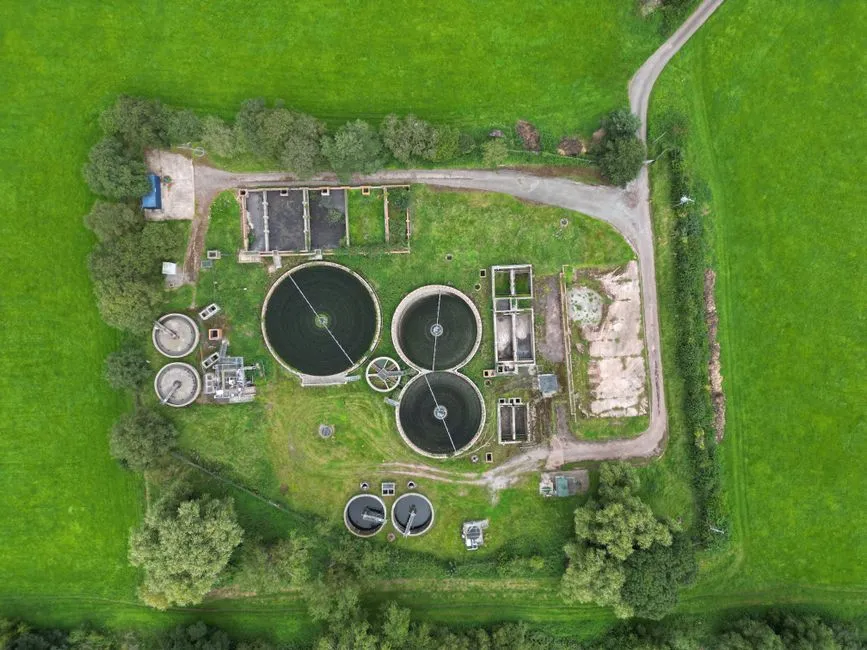
A gravity clarifier relies on the opposite physics from DAF. Flocculated or naturally dense particles settle under gravity to the bottom of the tank and are removed as sludge, while clarified water overflows a weir or launder at the top (S2, S4). A lamella clarifier accelerates that process by stacking inclined plates inside the tank, which shortens the effective settling path and raises the surface loading rate per unit footprint. The HydropureWater high-efficiency sedimentation tank combines sludge recirculation, flocculation, and inclined-plate separation to deliver higher surface loading rates and reduced chemical consumption compared with a conventional clarifier, in a compact package that is well suited to metal-fabrication and mill washwater duties.
The trade-off is well documented: DAF removes flocculated particles that float; sedimentation removes particles that sink. Depending on the wastewater chemistry, a DAF can also produce a bottom sludge layer from chemicals that do not float (S2), so the two processes are not perfectly orthogonal in practice. Clarifiers do not need a compressor, which removes a meaningful slice of OPEX and a meaningful slice of cold-weather risk on a remote Trapper Creek site. The disadvantages are real too: a conventional clarifier typically has a larger footprint than DAF, and settling kinetics slow as water viscosity rises in cold feed, which compresses performance in winter. The cold-water effect is a qualitative risk the engineer must price into the design margin — the supplied research does not quantify the viscosity penalty, so request cold-weather performance data from the supplier rather than assume a number.
DAF vs Clarifier: The 2026 Comparison That Drives the Decision
The table below consolidates the parameters a factory buyer in Trapper Creek actually needs in 2026, on a single sheet that can be lifted into a project memo. The mechanism, footprint, and sludge rows are grounded in the supplied research (S2, S4); the hydraulic-loading rows are drawn from the supplier's standard model range and the lamella surface-loading specification. The cold-climate row is qualitative because the research does not supply a defensible number, and the energy row flags the compressor penalty without inventing a kW value.
| Parameter | DAF (Dissolved Air Flotation) | Lamella / Conventional Clarifier |
|---|---|---|
| Mechanism | Micro-bubbles attach to flocculated particles and float them to the surface for skimming (S2, S4) | Particles settle under gravity to the bottom and are removed as sludge; clarified water overflows (S2, S4) |
| Footprint | Smaller than a normal clarifier; modular components allow easy installation and setup (S4) | Larger footprint, partially closed by inclined-plate (lamella) design |
| Hydraulic loading | HydropureWater DAF line covers 4–300 m³/h across 13 standard models | Lamella units rated at 20–40 m/h surface loading |
| Sludge consistency | Thicker sludge than sedimentation (S4); reduces downstream dewatering cost | Typically requires a thickener or sludge conditioning step before dewatering |
| Energy | Higher OPEX; compressed air required (S2) — request compressor kW from supplier | Lower OPEX; no compressor required (S2) |
| Chemicals | Coagulants/flocculants: alum, poly aluminium chloride, poly aluminium sulphate, ferric chloride, bentonite, organic polymers (S2) | Same coagulant/flocculant family; no compressor chemistry to manage |
| Start-up | Rapid start-up (S4) — advantage after a winter shut-down or campaign restart | Slower start-up; longer residence time to develop a stable blanket |
| Cold-climate risk | Enclosed tank protects the process; cold feed still raises viscosity but bubbles are less viscosity-sensitive than settling | Settling rate drops as cold feed viscosity rises — request cold-weather performance data from supplier |
| Best-fit feed | Variable flow, FOG/hydrocarbons, shock loads, small pad, modular relocation (S2, S4) | Steady flow, readily settleable solids, large pad, energy cost dominates |
Two patterns from the table are worth pulling out for a 2026 spec. First, the sludge row is a hidden cost driver: DAF's thicker sludge reduces downstream dewatering cost (S4), which matters when the dewatering unit is a plate and frame filter press sized off sludge solids percent. Pair the DAF with a plate and frame filter press sized to the DAF's expected solids capture rather than a clarifier's thinner underflow, and the OPEX advantage shows up in polymer and haul-off cost. Second, the energy row is not symmetric: DAF's compressed-air requirement is a parasitic load that a clarifier simply does not have, so on a Trapper Creek site that pays for diesel generation, the compressor kWh per cubic metre treated belongs in the bid tab. Request that number from the supplier with the bid, do not assume it. The automatic chemical dosing system should also be specified alongside either unit so polymer consumption can be controlled against the cold-feed viscosity swing.
Match the Choice to Your Trapper Creek Scenario
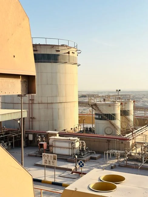
Three site pictures cover most of what a Trapper Creek engineer will see in 2026, and each one resolves to a different stack of equipment.
Scenario A — small footprint, variable flow, FOG or oily sheen present. The default here is a DAF unit. The documented advantages — smaller footprint, modular components for easy installation, rapid start-up, and the ability to remove suspended solids, FOG, hydrocarbons, and shock loads (S2, S4) — line up with what a tight, variable-feed site actually needs. DAF's documented FOG and hydrocarbon removal is a real specification input on a metals-fabrication wash bay where cutting fluids and hydraulic oil show up in the wastewater.
Scenario B — large open pad, steady gravity-settleable solids, energy cost matters. The default here is a lamella clarifier. No compressor is required, DAF is reported to use more energy than sedimentation (S2), and a clarifier's lower OPEX shows up immediately on a site where electricity or diesel fuel is a real line item. Where the feed is steady and the solids settle readily, the clarifier's larger footprint is a fair trade for the energy and simplicity gain.
Scenario C — high total suspended solids with a metals removal target downstream. The default here is a hybrid: a clarifier for bulk roughing followed by a DAF for polishing. This is a documented industry pattern for the mining and metals sector, where the clarifier knocks down the bulk TSS cheaply and the DAF polishes to the metals target the downstream process or discharge permit requires (S2). On the chemical side, where soluble silica is a concern in the feed, polymeric or colloidal aluminium coagulants are more effective than monomeric aluminium (S2) — pass that to the dosing system spec so the polymer program is set up correctly on day one. For broader context on how a similar hybrid stacks up against a single-unit spec at a comparable remote site, see the DAF or clarifier for mining/metals wastewater in Taylor, US guide, and for the pretreatment side of the same compliance picture, the mining pretreatment compliance near Travellers Rest piece covers the discharge-permit framing.
2026 Procurement, Compliance and Cold-Climate Risk Checklist
The supplied research confirms the process choices but does not list specific 40 CFR Part 440 numeric effluent limits or Alaska APDES mining effluent numbers, so the engineer must pull those from the relevant subcategory and the current permit before signing a PO. The checklist below is the set of items to verify, not the numbers themselves.
- Compliance inputs to request from the supplier: a written confirmation that the proposed unit supports 40 CFR Part 440 effluent guidelines for the relevant mining or ore processing subcategory, and the Alaska APDES permit limits the unit is sized against. The research does not supply these numbers — the supplier must.
- Cold-climate qualitative checks: enclosure heating for the DAF saturator and skimmer drive, pipe freeze protection for the lamella underflow, polymer pump performance at sub-zero ambient, compressor reliability in sub-zero ambient, and operator response time on a remote site. These are inputs to verify, not assumed pass/fail criteria.
- Sludge handling integration: specify the downstream dewatering unit so the DAF-thick-sludge benefit (S4) is actually captured. Pair the DAF with a plate and frame filter press sized to the DAF's expected solids percent, and specify the sludge transfer pump and polymer conditioning stage between them.
- Bid tab inputs to request: hydraulic loading at the design feed temperature, polymer consumption in kg/m³ at design TSS, expected sludge solids percent, compressor kW at the design air-to-solids ratio, cold-weather performance data (or a clearly stated operating envelope), and a reference list of mining/metals installations in cold climates. These belong in the supplier's proposal before the PO is cut. The same framework is laid out in the 2026 factory guide for Taylor, US for parallel reading.
Frequently Asked Questions
What is the realistic 2026 budget range for a DAF or lamella clarifier on a Trapper Creek mining site?
The supplied research does not publish a price for either unit, and freight into Trapper Creek, Alaska is a meaningful cost line that no catalogue number captures. Request an itemised bid that separates the unit price, freight to site, installation, and commissioning, then compare on a $/m³-treated basis at the design flow rather than on the sticker price.
How do I size a DAF or clarifier for a Trapper Creek metals plant in 2026?
Size off the design flow, the design TSS, the design feed temperature, and the target effluent TSS or metals limit. The HydropureWater DAF model line covers 4–300 m³/h across 13 standard models, and the lamella units are rated at 20–40 m/h surface loading. Ask the supplier to run a mass balance at your design TSS and feed temperature, and to confirm the unit will meet the target at the coldest expected feed condition — not at 20 °C bench data.
Does a DAF or a clarifier handle cold Trapper Creek winter feed better?
Both technologies degrade as feed viscosity rises in cold water, but they degrade in different ways. DAF's micro-bubble attachment is less viscosity-sensitive than gravity settling, and the enclosed DAF tank protects the process from ambient cold. A clarifier's settling rate drops as cold feed viscosity rises, which compresses the operating window. Treat cold-weather performance data as a mandatory deliverable from the supplier rather than a footnote in the bid.
What compliance risk should a 2026 PO carry for 40 CFR Part 440 and Alaska APDES?
40 CFR Part 440 effluent guidelines and the Alaska APDES permit set the numeric limits for the relevant mining or ore processing subcategory, and the supplied research does not list those numbers. The compliance risk is that the unit is sized against a generic curve instead of the actual permit limit, and the supplier's performance guarantee should be written against the permit numbers, not against a generic TSS removal percentage. Confirm the subcategory, pull the current permit limits, and put both in the supplier's guarantee.