Why the plastics and rubber stream is its own decision
The plastics and rubber wastewater stream is chemically distinct from the food, dairy, or mining streams often used in generic DAF-versus-clarifier comparisons. A polymer finishing line sheds pellet fines, plasticizer residues, silicone- or wax-based mold release agents, latex carryover from dipping lines, uncured rubber crumb, and light extrusion oils. These contaminants tend to be low-density or emulsified; consequently, a clarifier calibrated for settleable inerts reads them as non-settleable and passes them downstream.
EPA's Process Design Manual for Suspended Solids Removal (1975) treats flotation and gravity sedimentation as separate unit processes rather than functional equivalents. Because any industry-wide performance data for DAF or clarifiers was collected on different feeds, a jar test of your specific stream is the only defensible input for sizing equipment on a Union Grove polymer line. A working overview of the compliance framing is in this plastics and rubber pretreatment compliance guide.
How DAF works on a polymer finishing line
A DAF clarifier utilizes a saturated recycle stream that depressurizes inside the tank to release a cloud of microbubbles in the 30–50 micron range. These bubbles attach to conditioned floc particles generated by coagulation and flocculation upstream, causing the bubble-particle aggregates to rise to the surface for removal by a paddle skimmer. Hahn's Fundamentals of Wastewater Flotation (2010) reports that flotation systems can reach 90% oil removal when air-to-solids ratio, hydraulic loading, and chemical conditioning are optimized. On a polymer line, DAF pulls emulsified release agents, plasticizer residues, low-density latex, and most synthetic fines out of the water column—the exact fraction a clarifier would miss.
| DAF design parameter | Typical operating range | Source |
|---|---|---|
| Microbubble size | 30–50 microns | SigmaDAF/Clearwater product literature (2026) |
| Oil removal benchmark | ~90% on conditioned industrial feed | Hahn, Fundamentals of Wastewater Flotation (2010) |
| Key design variables | Air/solids ratio, hydraulic loading, chemical conditioning | Hahn (2010) |
| Process reference | Section 7.8 (Flotation) | EPA Process Design Manual, 1975 |
Cationic flocculants used to condition wastewater before a DAF can react with anionic latex dispersions, so feed chemistry must be bench-tested on your specific line. The design logic for polymer-rich streams is covered in more detail in this DAF design guide for polymer-rich industrial streams, and a related DAF design walkthrough details the jar-test-to-spec sequence on a different polymer stream.
How a clarifier performs on the same stream
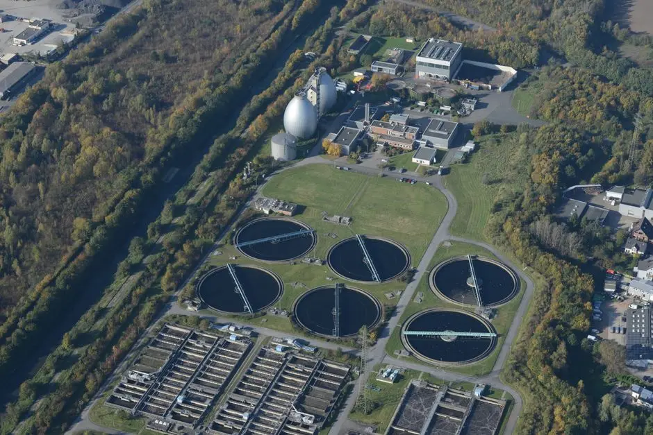
A clarifier is a gravity sedimentation vessel where heavier-than-water particles drop to the bottom under quiescent conditions to be raked to a central sludge draw, while clarified water overflows a peripheral launder. The formal reference is EPA Process Design Manual Table 7-2, which defines typical design parameters for primary clarifiers. The modern, compact expression of this physics is the inclined-plate, or lamella, clarifier, which uses steeply inclined plates to multiply the effective settling area; the HydropureWater high-efficiency sedimentation tank specification describes surface loadings in the 20–40 m/h band, along with chemical savings of up to 30% versus a conventional basin on compatible feeds. A lamella clarifier functions best as a polishing or sludge-thickening stage downstream of a DAF on a polymer line.
A clarifier alone is appropriate on a plastics or rubber site only when streams are dominated by inert mineral filler such as talc, calcium carbonate, or titanium dioxide, plus grinding dust, with very little free or emulsified FOG. It fails when handling meaningful plasticizer or release-agent loads, as the floatable fraction exits in the effluent and arrives at the local POTW as a surcharge. A lamella clarifier should be treated as a downstream polishing or thickening stage rather than the sole primary separator when the influent carries FOG.
Side-by-side: DAF vs clarifier on the parameters that matter
The table below summarizes the parameters that influence vendor conversations for a Union Grove polymer line. Because the Ecologix oil/grease benchmarks (95% DAF versus 70% clarifier) are derived from food processing, these values serve only as order-of-magnitude context; the specific performance requirements for your plant must be confirmed via a jar test of your effluent.
| Parameter | DAF | Gravity / Lamella Clarifier |
|---|---|---|
| Removal mechanism | Microbubble attachment and buoyancy rise | Gravity sedimentation; lamella adds inclined-plate area |
| Target contaminant | Emulsified oils, FOG, plasticizer, latex, low-density fines (Ecologix cites 95% oil/grease removal on a food-processing feed) | Settleable inerts, heavy fillers, grinding dust (Ecologix cites 90% sediment reduction at a mining site) |
| Microbubble size / surface loading | 30–50 micron microbubbles (SigmaDAF/Clearwater, 2026) | 20–40 m/h surface loading on lamella geometry (HydropureWater high-efficiency sedimentation tank specification) |
| Hydraulic tolerance | Tolerates feed swings when paired with equalization; sensitive to air/solids ratio | Sensitive to hydraulic surges; benefits from upstream equalization |
| Footprint | Compact for the same flow on FOG-bearing streams | Conventional basin is large; lamella geometry is compact |
| Chemical demand | Coagulant plus flocculant; feed-sensitive on anionic latex systems | Lower on inert streams; flocculant aid when used as polishing |
| OPEX drivers | Air compressor, recycle pump, polymer dose, sludge handling | Sludge rake, polymer aid dose, sludge handling |
| Polymer-line fit | Correct primary for release-agent, plasticizer, and latex streams | Correct downstream polishing and sludge-thickening stage; not the lone primary on a FOG-bearing stream |
| Plasticizer/latex carryover | Needs tuned coagulation; not a magic bullet | Will not remove floatable plasticizer or latex without upstream removal |
When a polymer line requires both units, the practical train is DAF first, followed by the clarifier. A vendor-spec DAF system should be evaluated against your jar-test results and local POTW discharge limits rather than generic industry benchmarks.
The 2026 default layout for Union Grove polymer plants
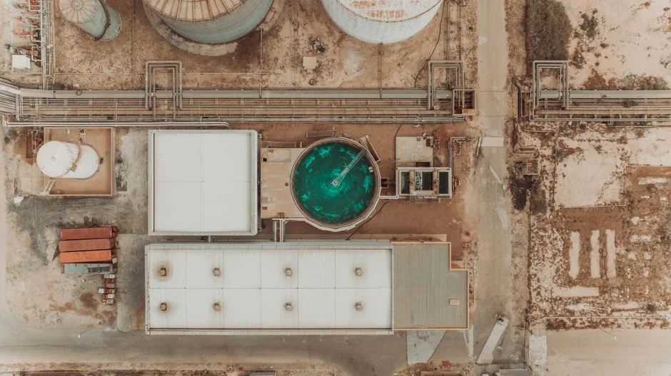
The defensible default for a Union Grove plastics or rubber facility in 2026 is a DAF unit as the primary separator, with a lamella or solids-contact clarifier in the polishing or sludge-thickening slot. EPA's Process Design Manual sequences the train as chemical treatment followed by either flotation or sedimentation; the manual treats these as complementary unit processes, supporting the common industrial practice of stacking DAF and clarifiers rather than choosing between them.
Apply this four-line mental test when evaluating equipment:
- High FOG or plasticizer load: specify DAF as the primary.
- Heavy inert filler, low FOG: a clarifier can carry the load.
- Both fractions present: DAF first, clarifier second.
- Variable influent: put an equalization tank upstream of either unit to stabilize wastewater characteristics.
Union Grove plants discharge under Wisconsin pretreatment rules, where the local POTW sets the specific TSS and FOG limits. Because the buyer is responsible for the design margin required to meet these limits, bench- and pilot-scale results belong in the equipment specification. Pretreatment framing for a different Wisconsin-area context is laid out in this nearby-plant pretreatment guide.
Choosing a unit in 2026: a 4-profile decision matrix
Map your plant to one of the following four common Union Grove-area profiles to identify the appropriate treatment train. This matrix serves as decision support and does not replace a jar test on your actual stream, particularly for verifying polymer reactions between cationic flocculants and anionic latex dispersions.
| Plant profile | Dominant contaminants | DAF-only | Clarifier-only | DAF → lamella (recommended) |
|---|---|---|---|---|
| Plastic extrusion line | Release agents, plasticizer residues, light extrusion oils | Workable, but sludge handling is the bottleneck | Will pass floatable FOG to the POTW | Default choice |
| Rubber molding / dipping | Latex carryover, carbon black fines, mold-release oils | Workable if latex chemistry is bench-checked | Fails on the floatable fraction | Default choice; jar test the polymer interaction |
| Plastics recycling wash line | Pellet fines, label adhesives, light plastics | Removes fines; struggles on heavy label adhesive | Misses the low-density fraction | Default choice, often with a pre-screen ahead of DAF |
| Masterbatch / compounding | Heavy mineral filler (CaCO₃, talc, TiO₂), low FOG | Over-specified for the load | Workable if FOG is well-controlled | Optional polish; clarifier alone is acceptable |
For a polymer line with non-trivial FOG or latex, the practical hardware to evaluate is a DAF system ahead of a lamella clarifier, with an automatic polymer and coagulant dosing skid upstream to ensure reproducible flocculation. A peer Cadillac plastics and rubber DAF vs clarifier guide applies this same matrix to a different plant mix in Michigan.
Frequently Asked Questions
Can a Union Grove plastics or rubber plant install a clarifier-only system in 2026?
Usually no, unless the stream is dominated by heavy inert filler with minimal FOG, plasticizer, or latex carryover. A clarifier alone will pass the floatable fraction through to the local POTW, likely resulting in a violation of Wisconsin pretreatment limits on a polymer finishing line. Always run a jar test first to confirm the floatable fraction is small.
What budget range or cost drivers should we expect for a 2026 DAF or clarifier installation?
Pricing varies based on capacity, material of construction (304SS versus 316SS for chloride exposure), chemical-dosing scope, and sludge-handling design. Request quotes from shortlisted vendors based on the same flow, influent specification, and effluent target. Key cost drivers include: design flow and peak factor, materials of construction, coagulant and flocculant dose assumptions, sludge concentration targets, and any included equalization tank.
How do we choose a supplier and what lead time should we plan for in 2026?
Shortlist vendors that manufacture in-house (e.g., Clearwater/SigmaDAF documentation notes in-house DAF manufacturing in Brown Deer, WI) and request references for Wisconsin or Upper-Midwest installations. Secure a written lead time for the skid, controls, and chemical-dose skids as separate line items, as automation panels and dosing skids often have different lead times than the tank itself.
Who owns the jar test and the pilot, and why does EPA Chapter 7 matter for compliance?
The jar test and any pilot studies are the buyer's responsibility, as the vendor cannot certify performance on a stream they have not evaluated. Cite EPA's Process Design Manual for Suspended Solids Removal (1975)—specifically Chapter 7.8 for flotation and Tables 7-2/7-3