Clarifier Roles in Industrial Wastewater Treatment
Clarification is gravity-driven removal of suspended solids from wastewater, with a secondary function of removing accumulated scum and floating matter from the surface (Fehr Graham, 2025). In an industrial wastewater treatment plant, the clarifier is assigned to one of three roles: primary, secondary, or dedicated industrial-waste settling. Primary clarifiers sit ahead of biological treatment and remove settleable solids, oil, and grease from raw wastewater. Secondary clarifiers separate flocculated biomass from the treated liquid and split the flow into return activated sludge and waste activated sludge streams. Industrial-waste clarifiers handle streams with significant industrial contributions, and the Iowa DNR rules at §16.3.2.4.3 require their overflow rates to be confirmed by pilot studies, data from similar systems, or literature.
Final settling tanks that follow an activated-sludge process carry a dual obligation: they must thicken as well as separate, because return-sludge recirculation rates are high and the sludge blanket sits close to the overflow weirs (Iowa DNR §16.3.2.4.2). Wet-weather clarifiers follow the same design principles as conventional primary and secondary clarifiers but must handle grit washout, extremely low sludge volume index, and transient flows that diminish performance (Fehr Graham). Configuration is largely a function of role: circular units dominate secondary duty, while primary duty is commonly served by both circular and rectangular tanks.
Assigning the wrong role to a tank cascades through every downstream design decision. A primary tank built to secondary depth and overflow rates is over-built for its job; a secondary tank sized as a primary will lose sludge blanket during peak hour flow. The role locks the applicable side water depth, the surface overflow rate, the solids loading limit, and the type of sludge withdrawal system, which is why the role is the first decision in any defensible basis-of-design.
Design Criteria That Govern Clarifier Sizing
Iowa DNR Chapter 16 publishes a numeric spine for settling-tank design that a permitting authority will recognize. Side water depth is at least 7 ft for primary settling tanks, at least 12 ft for tanks following the activated-sludge process, and at least 10 ft for tanks following fixed-film reactors (Iowa DNR §16.3.1). A 10 ft side water depth is also permitted for activated-sludge tanks only when the BOD load is below 340 lb/d and the clarifier is followed by a 5-ft pond.
Surface overflow rates must be evaluated at both the average wet-weather flow (AWW) and the peak hour wet-weather flow (PHWW), with the larger required surface area governing. The Iowa DNR caps are 1,000 gpd/sf AWW and 1,500 gpd/sf PHWW for primary settling tanks, and 900 gpd/sf AWW plus 1,200 gpd/sf PHWW for intermediate tanks following the carbonaceous stage of a separate-stage nitrification train. For intermediate tanks after other units, the cap is 1,500 gpd/sf based on PHWW (Iowa DNR §§16.3.2.2–16.3.2.3).
Final settling tanks for activated-sludge processes carry both a hydraulic cap and a solids-loading cap. The hydraulic cap at PHWW depends on the process variant: 1,200 gpd/sf for contact stabilization and high-purity oxygen with primary settling, 1,000 gpd/sf for extended aeration, and 800 gpd/sf for separate nitrification. The solids-loading cap is 30 lb/d/sf at AWW and 50 lb/d/sf at PHWW for every activated-sludge variant, and the clarifier must be sized to the largest of the four loading conditions (Iowa DNR §16.3.2.4.2). For fixed-film final tanks, the cap is 1,200 gpd/sf at PHWW, increasable when chemical addition is justified by pilot or similar-system data (Iowa DNR §16.3.2.4.1).
Weir loadings are capped at 10,000 gpd/lf for plants designed for AWW flows of 1.0 mgd or less, with up to 15,000 gpd/lf permitted for larger plants; peripheral weirs should sit at least 1 ft from the wall or be paired with baffles to limit wall effects (Iowa DNR §§16.3.4.2–16.3.4.3). Freeboard is at least 6 in above surrounding grade and at least 12 in vertical, with additional freeboard or wind screens recommended for large tanks in high-wind locations (Iowa DNR §16.3.6). For cross-cutting sizing context, the AOP system design guide 2026 covers how these clarifier outflows feed downstream oxidation stages.
| Parameter | Primary | Intermediate (post carbonaceous nitrification) | Final — Activated Sludge | Final — Fixed Film |
|---|---|---|---|---|
| Side water depth (min) | 7 ft | 7 ft | 12 ft (10 ft if BOD <340 lb/d and followed by 5-ft pond) | 10 ft |
| Surface overflow rate at AWW | 1,000 gpd/sf | 900 gpd/sf | Set by solids-loading cap (30 lb/d/sf) | Not specified |
| Surface overflow rate at PHWW | 1,500 gpd/sf | 1,200 gpd/sf | 800–1,200 gpd/sf by process variant | 1,200 gpd/sf |
| Solids loading at AWW / PHWW | — | — | 30 / 50 lb/d/sf | — |
| Weir loading (≤1.0 mgd AWW) | 10,000 gpd/lf | 10,000 gpd/lf | 10,000 gpd/lf | 10,000 gpd/lf |
| Weir loading (>1.0 mgd AWW) | 15,000 gpd/lf | 15,000 gpd/lf | 15,000 gpd/lf | 15,000 gpd/lf |
| Source | Iowa DNR Chapter 16 (2025-02) | |||
Configuration, Geometry, and Sludge-Handling Details

The sizing numbers in the table must be translated into geometry before they become a purchase order. The Iowa DNR requires multiple units capable of independent operation, with flow-splitting devices such as valves, gates, and splitter boxes to proportion flow to each unit (§§16.2.1–16.2.2). Inlet structures must dissipate inlet velocity, distribute flow both horizontally and vertically, prevent short-circuiting, and keep channel velocity at or above 1 ft/s at half the AWW flow; corner pockets are not allowed, and provisions for floating-material removal are required (§16.3.3).
Overflow weirs must be readily adjustable, serrated with V-notches, and located to optimize hydraulic detention time while minimizing short-circuiting; interior weirs are permitted only when paired with effective scum removal (§§16.3.4.1–16.3.4.2). Sludge hoppers must have a minimum side-wall slope of 1.7 vertical to 1 horizontal, smooth walls with rounded corners, and a hopper bottom plan dimension no greater than 2 ft; extra-depth hoppers intended for sludge thickening are explicitly not acceptable (§16.4.2.1). Each hopper needs an individual valved withdrawal line at least 6 in in diameter, at least 30 in of static head to maintain 3 ft/s withdrawal velocity, and rodding or backflushing provisions; air-lift sludge removal is not approved for primary sludges (§§16.4.2.3–16.4.2.4).
Drive unit specification deserves the same rigor as the hydraulic criteria. A clarifier typically operates at one torque value for 90–98% of its running time, so the drive must be specified with separate running, alarm, and shut-off torque ratings matched to the intended use (Monroe Environmental, 2025). Side water depth is a primary lever for preventing sludge blanket washout during prolonged wet-weather events, with 4.3–5 m recommended for high-flow conditions (Fehr Graham). A practical belt filter press field guide covers what happens to clarifier underflow once it leaves the hopper and reaches the dewatering stage.
Wet-Weather, Chemical Enhancement, and Industrial-Waste Specifics
Wet weather stresses clarifiers in three measurable ways: grit washout from sewers and grit chambers, an extremely low sludge volume index in the secondary train, and transient flows that distort the sludge blanket (Fehr Graham). Counter-measures documented for these conditions include ballasted flocculation, which adds a coagulant and micro-sand ballast to primary clarifier influent, and inclined tube (lamella) inserts that shorten the effective settling path. Chemically enhanced primary treatment with coagulants is a feasible alternative to expanding biological capacity during unexpected wet-weather peaks.
When chemical coagulants are added, the Iowa DNR allows the surface overflow rates in §16.3.2 to be increased, but only with supporting evidence from pilot studies, similar systems already in operation, or published literature (§16.3.2.1). For industrial-waste settling tanks and domestic tanks with significant industrial contributions, the same rule applies: rates shall not exceed the caps in §§16.3.2.4.1 and 16.3.2.4.2, and rates should be confirmed by pilot studies, similar-system data, or literature (§16.3.2.4.3). For streams with appreciable industrial waste, the default 30–35% BOD removal expected for normal domestic sewage is replaced by a project-specific value derived from laboratory tests and actual settling data (§16.3.2.2).
Wet-weather flexibility is also built into the upstream side of the train: a high-solids separation facility can be designed to operate as a primary clarifier during wet weather, supporting operational flexibility without a duplicate tank (Fehr Graham). When oily streams from a metals or mining operation are in play, the DAF vs clarifier for mining/metals guide covers when the upstream unit itself should be a flotation cell rather than a clarifier.
When a DAF System Is the Better Choice Than a Clarifier
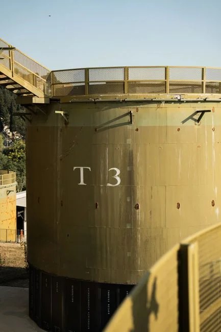
The choice between a dissolved air flotation system and a clarifier is driven by the contaminant profile, not by a single best technology. DAF systems use air bubbles to float light particles, oils, and greases to the surface for skimming, while clarifiers rely on gravity sedimentation to settle heavier solids to the bottom as sludge (Ecologix, 2026). Two industrial cases from the research make the trade-off concrete: a food-processing plant with high oil content achieved 95% oil and grease removal on a DAF compared with 70% on a clarifier for the same stream, while a mining facility with heavy sediment loads chose a clarifier and achieved 90% solids reduction at lower cost.
Clarifiers generally have lower operational costs; DAF systems can be more cost-effective for specific contaminants such as oils and greases, especially when the cost of lost product or downstream fouling is included (Ecologix, 2026). Hybrid DAF-then-clarifier trains can address complex streams by combining oil and grease removal with downstream sedimentation. The selection drivers are influent contaminant character (oils and FOG versus heavy solids), footprint constraints, hydraulic loading, and target effluent quality. A packaged dissolved air flotation system is the typical equipment package for the flotation half of such a train.
| Decision driver | Favors clarifier | Favors DAF |
|---|---|---|
| Dominant contaminant | Heavy settleable solids | Oils, greases, fine colloids |
| Removal example (research) | Mining stream, 90% solids reduction at lower cost (Ecologix, 2026) | Food-processing stream, 95% oil and grease removal vs 70% on clarifier (Ecologix, 2026) |
| Footprint | Larger for a given flow | Compact for the same hydraulic load |
| Operating cost driver | Lower for heavy-solids duty | Higher (air compressor, pumps) but offset by product recovery and effluent quality |
| Source | Ecologix Environmental Systems (2026) | |
Step-by-Step Selection Workflow for an Industrial Clarifier
A defensible basis-of-design follows a sequence, not a shopping list. Step 1 — Characterize the wastewater. Quantify the flow regime (AWW and PHWW), TSS, BOD or COD, FOG, particle size distribution, settleability, and temperature, because these set the applicable role and overflow rate (Iowa DNR §16.3.2). Step 2 — Assign the role. Lock the role as primary, intermediate, secondary, or industrial-waste settling, then bind the side water depth and the applicable overflow rate to that role (Iowa DNR §§16.3.1, 16.3.2.2–16.3.2.4.3). Step 3 — Compute required surface area. Size to the larger of the AWW and PHWW overflow rates, and for activated-sludge duty to the largest of the four hydraulic and solids-loading conditions (Iowa DNR §§16.3.2.2, 16.3.2.4.2).
Step 4 — Choose configuration. Select circular versus rectangular, peripheral versus center feed, and whether to add lamella tubes or ballasted flocculation based on footprint, retrofit constraints, and wet-weather exposure (Fehr Graham). Step 5 — Specify sludge and scum removal. Lock the hopper geometry, withdrawal-line size, drive torque ratings, scum collection, and instrumentation (Iowa DNR §§16.4.1–16.4.2.4; Monroe Environmental, 2025). Step 6 — Verify with pilot or jar testing, or with data from a similar operating facility, especially when industrial waste contributions are significant (Iowa DNR §§16.3.2.1, 16.3.2.4.3). For oily streams that may push the workflow toward flotation, the DAF troubleshooting guide covers operating issues once the unit is commissioned.
Frequently Asked Questions
What is the biggest sizing mistake engineers make on industrial clarifiers?
Computing surface area from the hydraulic overflow rate alone. For activated-sludge duty, the clarifier must be sized to the largest of four conditions: AWW and PHWW hydraulic loadings and AWW and PHWW solids loadings (30 and 50 lb/d/sf), and the larger required surface area governs (Iowa DNR §16.3.2.4.2).
How much does a clarifier cost compared with a DAF for the same flow?
The research compares cost qualitatively rather than publishing a unit price. Clarifiers generally have lower operational costs for heavy-solids duty, while DAF systems can be more cost-effective for oils and greases (Ecologix, 2026). For a defensible budget, request a per-unit capital cost for the chosen role and configuration and a per-kWh or per-pound-of-sludge operating cost from each shortlisted supplier, since both numbers depend on the contaminant profile and site constraints that the research does not specify.
When should we apply domestic clarifier design rates to an industrial waste stream?
Only as an upper bound. For industrial waste treatment facilities and domestic facilities with significant industrial contributions, the Iowa DNR caps the surface overflow rates at the values in §§16.3.2.4.1 and 16.3.2.4.2 and requires rates to be confirmed by pilot studies, data from similar systems already in operation, or literature data (§16.3.2.4.3). A supplier should be able to document similar-system performance for your specific contaminant class before any rate is increased.
How do we pick a clarifier supplier without getting locked into the wrong configuration?
Match the supplier's documented experience to your assigned role and regulatory framework, not just to flow capacity. A shortlist should include evidence of similar primary, secondary, or industrial-waste clarifiers in service, willingness to specify separate running, alarm, and shut-off drive torque ratings (Monroe Environmental, 2025), and the ability to support a chemical-enhancement pilot if you plan to operate above the standard rates. For a broader market view, the reliable wastewater treatment plant equipment suppliers 2026 buyer's guide frames the supplier-selection criteria against the same role-driven logic used in this article.
Related Equipment
- HydropureWater lamella clarifier — specifications, capacity range, and technical data
- automatic chemical dosing system — specifications, capacity range, and technical data