
Why Mumbai's semiconductor and data-hall water problem is different in 2026
Mumbai's municipal supply is monsoon-fed — Tansa, Bhatsa, Modak Sagar and Upper Vaitarna feed the system, and the same catchments serve domestic demand, a growing semiconductor packaging base in the Pune–Mumbai industrial belt, and a hyperscale data-hall build-out clustered around Navi Mumbai and the Mahape–Airoli corridor. A single failed monsoon hits fabs, data halls and the city's piped supply simultaneously, and the Mithi river outfall constraints mean that anything not recovered on-site eventually shows up in the same drainage channel that the city relies on for storm release.
Globally, 40% of existing fabs and over 40% of new fabs announced since 2021 are projected to sit in basins with high or extremely high water stress by 2030 (Lepawsky 2024, cited in TNFD, Feb 2026), and 45% of data centres globally are already in basins at high risk of water-availability disruption (Hajonides et al. 2025, cited in TNFD, Feb 2026) — the Mumbai–Pune belt sits squarely in that exposure window. The single most important ratio to defend in any 2026 capex paper is the feed leverage: for every 1 m³ of UPW produced, 1.4–1.6 m³ of municipal water is required (IDE Technologies 2024, cited in TNFD, Feb 2026). That multiplier is what turns a treatment-train decision into a board-level water-security decision.
The compliance stack: CPCB, MPCB and MCGM sewer tie-in
Three overlapping permit layers govern a 2026 fab or hyperscale site in Greater Mumbai, and they must be sequenced correctly or the design will land on the wrong number. Layer 1 is the national floor: CPCB's Effluent Discharge Standards (Schedule I) set industry-typical inlet and outlet limits for pH, TSS, BOD/COD, total nitrogen, fluoride and heavy metals. Treat these as the minimum, not the design target. Layer 2 is the site-specific permit: MPCB Consent to Operate (and Consent to Establish for greenfield sites) layers additional conditions on fluoride, total nitrogen, heavy metals, and increasingly on water-recovery percentage and ZLD status for new fabs. Layer 3 is the local discharge permit: the MCGM sewer tie-in governs what can be sent to the municipal sewer, including peak flow rates, prohibited substances and pre-treatment standards; for an indirect discharger the MCGM tie-in often carries the tightest substance numbers on a specific stream, because the sewer feeds coastal outfalls. The 2026 watch-list parameters are fluoride (from UPW reject and HF-bearing etchants), phosphate and zinc (from cooling-water programmes), and PFAS indicators. The Munich/AbwV pattern in the parallel engineering guide recommends 20–30% design headroom under the permit line, and the same approach applies here — the 2024–2026 revision cycles in comparable regimes are explicitly tightening fluoride, total nitrogen and COD envelopes. PFAS handling should be designed in from day one: legacy photoresist, etch chemistries and AFFF sources put PFAS on India's 2026 watch list, with the global direction (TNFD, Feb 2026; draft EU PFAS restriction) moving toward tighter PFOA/PFOS indicators. Segregate a PFAS-bearing stream even if a numeric limit is not yet enforced.
| Layer | Authority | Instrument | Watch-list parameters (2026) |
|---|---|---|---|
| 1 — National floor | CPCB | Effluent Discharge Standards, Schedule I | pH, TSS, BOD/COD, total N, fluoride, heavy metals |
| 2 — Site-specific | MPCB | Consent to Establish / Consent to Operate | Fluoride, total N, heavy metals, recovery %, ZLD status |
| 3 — Local discharge | MCGM | Sewer tie-in / indirect-discharger permit | Peak flow, prohibited substances, pre-treatment standards |
| Cross-cutting | Draft / watch-list | PFAS indicators (PFOA/PFOS family) | Segregate even where not numerically required |
Stream inventory: what actually comes out of a Mumbai fab or data hall
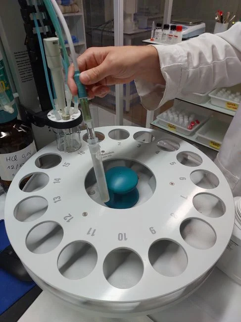
Designing one combined "wastewater" line for a back-end fab or a hyperscale hall is the most common engineering error; the streams have different chemistries, different reuse economics and different peak-to-average ratios, and they should be kept apart at the P&ID stage. Stream 1 is UPW reject — dominant by volume, loaded with fluoride, silica and traces of boron, and the single biggest hydraulic and recovery lever on a fab site. Stream 2 is cooling-tower blowdown, typically 4–8% of recirculation rate (TNFD, Feb 2026), carrying phosphate from scale/corrosion programmes, zinc and microbiocide residuals; on a data-hall-heavy site this is the largest recoverable hydraulic stream. Stream 3 is CMP effluent, with high suspended solids (silica, ceria, alumina slurries) plus trace copper, arriving as episodic batches that must be equalised before any membrane. Stream 4 is scrubber-quench, acidic, with dissolved metals (Fe, Cu, Ni, Zn) and (depending on chemistry) nitrate or sulfate, and it must branch into its own neutralisation and precipitation train. Stream 5 is adiabatic or humidifier bleed, which is data-hall-specific: low TDS but high in microbiocide residuals, and a candidate for direct RO/UV reuse rather than sewer discharge. Stream 6 is domestic and sanitary effluent from the same site, with conventional BOD/COD/nitrogen load that must be biologically treated before sewer discharge; keep it on its own line so a chemical upset in Streams 1–4 does not knock out the biological step.
| Stream | Source | Key contaminants | Reuse pathway |
|---|---|---|---|
| UPW reject | Polishing-loop bleed, fab | Fluoride, silica, boron | RO + EDI → cooling make-up, lower-grade rinses |
| Cooling-tower blowdown | HVAC, data hall | Phosphate, zinc, biocides | Side-stream softening + RO, ≥80% reuse |
| CMP effluent | Back-end planarisation | Silica/ceria/alumina slurries, Cu | Equalise → clarifier → main reclaim loop |
| Scrubber-quench | Wet scrubbers, etch | Fe, Cu, Ni, Zn, nitrate/sulfate | Neutralise + DAF + precipitation, then reclaim |
| Adiabatic / humidifier bleed | Data hall humidification | Biocide residuals, low TDS | RO + UV → reuse in cooling loop |
| Sanitary / domestic | Site occupancy | BOD, COD, N, P | Biological treatment → MCGM sewer |
The 2026 treatment train for a Mumbai back-end fab or data-hall site
The actual P&ID for a 2026 site starts with equalisation, because without slug-load smoothing nothing downstream survives a CMP batch or a scrubber dump. A lined balance tank with PLC-controlled pH adjustment, ORP monitoring and flow-paced coagulant dosing should be sized for 30–60 minutes of hydraulic retention at peak shift flows so downstream units see a steady influent. Step 2 is a lamella clarifier for stream equalisation at 20–40 m/h hydraulic surface loading, followed by a multimedia filter (sand + anthracite + garnet, typically 0.8–1.2 m bed depth) to bring SDI below 5 ahead of any membrane. Step 3 is the membrane core: PVDF ultrafiltration as RO pre-treatment at 0.03 µm, then an industrial RO skid for UPW-reject and blowdown recovery sized at 75–85% recovery, with EDI polishing of RO permeate for the higher-purity reuse loops (cooling-tower make-up, scrubber pre-wash, lower-grade rinse). Step 4 is activated carbon plus selective ion exchange for residual fluoride and trace heavy metals, and a chlorine dioxide generator for the recycled cooling loop (or UV) for microbial control, since both avoid the trihalomethane formation that comes from chlorination. The scrubber-quench branch runs separately: neutralisation in a FRP/dual-laminate tank, a DAF system for the scrubber-quench branch to lift entrained FOG and floated solids, then hydroxide precipitation of dissolved metals (Fe, Cu, Ni, Zn) at pH 8.5–10.5 depending on the metal; the DAF subnatant rejoins the main equalisation tank for RO recovery. Sludge from the clarifier and DAF underflow routes to a plate-and-frame filter press for clarifier and DAF sludge dewatering, targeting cake dryness ≥35% DS for offsite disposal — in India, the cost swing between a wet and a dewatered cake is often larger than the chemical cost of the treatment train itself, and a PLC-controlled chemical dosing for pH and coagulant control keeps the dose tight enough that the sludge mass does not blow out.
Reuse versus ZLD: the 2026 decision framework
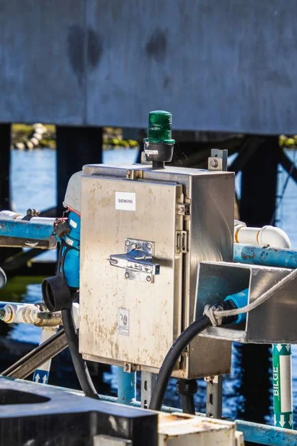
Decide stream by stream, not site-wide, because the cost of each additional recovery percentage is non-linear. Cooling-tower blowdown is the lowest-hanging reuse and should be designed first: 80–90% recovery is realistic after side-stream softening and RO, and on a data-hall-heavy site this is the largest single hydraulic and cost lever. UPW reject reuses at 60–75% in lower-grade loops (cooling-tower make-up, scrubber pre-wash, floor and CIP rinses); the 1.4–1.6× municipal-feed leverage (IDE Technologies 2024, cited in TNFD, Feb 2026) means every recovered m³ materially shifts the per-m³ cost line on a Mumbai water budget. Total site 65–80% recycling is the realistic envelope for a Mumbai back-end fab or data hall; best-in-class globally is 90% (TSMC Arizona, per the Munich engineering guide), but that is a hyperscale number driven by a greenfield site in a more water-stressed regulatory environment. Once site recycling exceeds ~85%, the binding constraint is brine management, not influent quality — at that point the conversation shifts to MVR-based low-temperature evaporation (LTE) ZLD, which is the technology India is now exhibiting at SEMICON India 2026 (SED press release, Business Standard, 9 Sept 2026; Yashobhoomi, 17–19 Sept 2026). The practical rule of thumb: design the train for 80% reuse and treat anything above that as a brine-handling problem, not a treatment-train problem.
| Stream | Recovery target | Configuration | Decision |
|---|---|---|---|
| Cooling-tower blowdown | 80–90% | Side-stream softening + RO | Recover first |
| UPW reject | 60–75% | RO + EDI, fluoride polishing | Recover to lower-grade loops |
| Adiabatic / humidifier bleed | 70–85% | RO + UV / ClO₂ | Recover to cooling loop |
| Site total | 65–80% | Stream-summed | Plan for 80%, treat above as brine problem |
| >85% site recovery | Brine-handling driven | MVR-LTE ZLD (SEMICON India 2026 signal) | ZLD conversation starts here |
What to ask a treatment-equipment supplier in 2026
The supplier meeting is where the design intent either survives or collapses, so the questions need to be specific. Ask for guaranteed permeate quality on UPW reject at 75–85% recovery, not "designed for" — recovery claims collapse at high TDS, and the contractual number is what hits MPCB at the next renewal. Ask for a full-sludge mass balance: kg DS/day, cake dryness target and offsite disposal classification, because in India the cost swing between 25% and 35% cake dryness is often larger than the chemical cost. Ask for power and steam per m³ treated, with the membrane-cleaning CIP frequency written in; that is the line item that hits OPEX for the next 10 years. Ask whether the RO and UF skid is pre-engineered and factory-tested — field assembly in Mumbai's monsoon window is a known schedule risk that is not visible in the FOB price. And ask for the MPCB consent conditions the system is designed to, plus the proposed monitoring and recording plan; a supplier who cannot answer that in 2026 is not yet aligned to the Indian market. For the broader engineering context, the 2026 Munich semiconductor and data-hall engineering guide covers the comparable European compliance stack, the Frankfurt compliance guide for the same process walks through the IED/AbwV/Genehmigungsbescheid layering, and the CMP wastewater treatment equipment cost comparison for 2026 gives stream-by-stream CAPEX benchmarks for equalisation, clarification and sludge handling.
Frequently Asked Questions
What does a 2026 reuse-and-ZLD treatment train actually cost in Mumbai?
No public benchmark gives a Mumbai-specific CAPEX number for a full back-end fab or hyperscale data-hall treatment train. What a buyer should request from each shortlisted supplier is a per-m³-treated CAPEX number (₹/m³/day), an OPEX number that includes power, steam, chemical, membrane replacement and sludge disposal, and a sludge mass balance at the design recovery target; only then can the proposals be compared on the same basis.
How do we shortlist treatment-equipment suppliers for a 2026 capex plan in India?
Shortlist on three verifiable criteria: a reference list of operating semiconductor or data-hall sites in India with named contacts, evidence that the RO/UF skid is pre-engineered and factory-tested rather than field-assembled, and a written response to the MPCB Consent to Operate conditions your site will face. A supplier who cannot produce all three in 2026 is not yet aligned to the Indian market; request the MVR-LTE ZLD reference set separately if the site is targeting above 85% recovery, since the SEMICON India 2026 signal (Business Standard, 9 Sept 2026) shows that evaporation-based ZLD is now a real Indian option, not an import-only line item.
Which streams should be segregated before designing the treatment train?
At minimum, segregate UPW reject, cooling-tower blowdown, CMP effluent, scrubber-quench, adiabatic or humidifier bleed, and sanitary effluent; each has a different chemistry, a different peak-to-average ratio, and a different reuse economics, and combining them upstream is the most common reason an Indian treatment train underperforms in commissioning.
What is the realistic site-recovery target for a Mumbai back-end fab or data hall in 2026?
65–80% total site recovery is the realistic envelope, with cooling-tower blowdown at 80–90%, UPW reject at 60–75% and adiabatic bleed at 70–85%; above ~85% the conversation shifts from treatment-train design to brine management and MVR-LTE evaporation, which is now being exhibited in India (SEMICON India 2026, 17–19 Sept 2026).