What "Advanced" Means for an Industrial Park in 2026
Advanced treatment in 2026 means a treatment train that runs beyond conventional secondary clarification: biological nutrient removal (A/O, A²/O, or submerged MBR) followed by a membrane or advanced-oxidation polish, paired with an instrumentation and SCADA layer that produces continuous, regulator-ready evidence rather than daily grab samples. This bar is no longer aspirational because 2026 discharge rules in the EU, U.S., China, and India all push toward online, auditable data: EPA's reissued NPDES general permit under the Clean Water Act, EU UWWTD 91/271/EEC for agglomerations above 2,000 p.e., China GB 18918-2002 Class 1A, and India CPCB consent conditions for inland discharge. The public-health sector has already shown what that architecture looks like at scale: WastewaterSCAN currently monitors roughly 150 sites across 40 U.S. states serving more than 39 million people, with a public data dashboard that any tenant or regulator can query (wastewaterscan.org, 2026). Springer (2025) frames on-line monitoring equipment as the practical bridge between a treatment plant and a regulator, citing Vanrolleghem and Lee (2003) as the canonical reference for the sensor stack that makes the bridge real. The same pattern — sensors to PLC to SCADA to a public dashboard — is what now differentiates a compliant park plant from a conventional one.
The Park-Scale Treatment Train, Stage by Stage
The default 2026 train for a multi-tenant park flows headworks → primary clarification or DAF → biological → membrane polish → disinfection → sludge handling, with chemical dosing tied to online sensors at every interface. The table below maps each stage to a unit operation, its operating envelope, and the data points a reviewer will ask about.
| Stage | Unit operation | Operating envelope | Key controls |
|---|---|---|---|
| Headworks | Rotary mechanical bar screen, 3–10 mm spacing | Continuous duty, fine screening | Differential level, ragging rate |
| Primary / FOG removal | DAF or lamella clarifier | DAF 4–300 m³/h, micro-bubble; lamella 20–40 m/h surface loading | Air-to-solids, polymer dose, surface loading |
| Biological | A/O contact oxidation or submerged MBR | Package A/O 1–80 m³/h; MBR 10–2,000 m³/day, <1 μm filtrate, ~60% smaller footprint than CAS | DO setpoint 1.5–2.5 mg/L, MLSS 6,000–10,000 mg/L (MBR), sludge age |
| Membrane polish | UF followed by RO for reuse | UF 2,000–40,000 L/h, 0.03 μm PVDF, accepts up to 300 NTU feed; RO up to 95% recovery | TMP, flux, recovery, conductivity |
| Disinfection | UV for reuse, on-site ClO₂ for discharge | UV dose ≥40 mJ/cm²; ClO₂ 50 g/h–20,000 g/h | Lamp intensity, residual, contact time |
| Sludge | Plate and frame filter press | 1–500 m² filter area, 18–25% dry cake target | Polymer dose, feed pressure, cycle time |
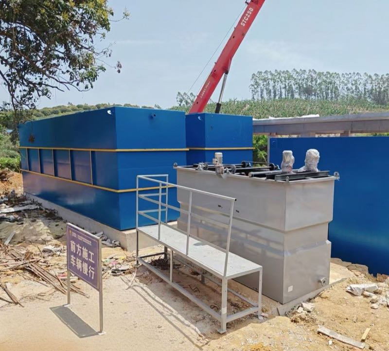
A typical headworks uses a rotary mechanical bar screen (GX series) with 3–10 mm bar spacing to strip rags, plastics, and fibrous debris before they reach the pumps. Parks with significant FOG, oil, or colloidal load — food processing, metalworking, petrochemical tenants — route flow through a dissolved air flotation unit (4–300 m³/h) that lifts floatables with micro-bubbles, or through a lamella clarifier where footprint is the binding constraint and chemical consumption needs to drop 20–30%. The biological stage then does the heavy lifting on organics and ammonia: a buried A/O package unit for smaller parks, a submerged MBR skid (10–2,000 m³/day) for parks that need reuse-grade water or are space-constrained, since MBR replaces a separate clarifier and produces filtrate below 1 μm. Ahead of any RO, a UF system (0.03 μm PVDF, 2,000–40,000 L/h) with automatic backwash and air scour protects the membranes from particulates and turbidity spikes up to 300 NTU. Disinfection splits by end use: a UV sterilizer at ≥40 mJ/cm² for reuse streams, where avoiding disinfection by-products matters, and on-site chlorine dioxide where a residual is required downstream. Sludge is dewatered on a plate-and-frame press to 18–25% dry solids before disposal, with the polymer-dose loop paired to feed solids via a dosing skid.
The Monitoring Layer That Makes It "Advanced"
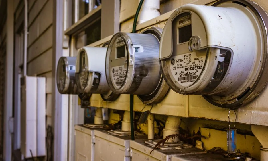
A treatment train without a monitoring layer is just equipment; a train with online sensors and a SCADA historian is the system a 2026 regulator accepts as evidence. The table below is the minimum sensor matrix a park plant should specify, with the data path that makes it auditable.
| Parameter | Sensor type | Location in train | Role |
|---|---|---|---|
| Flow | Parshall flume or magnetic flow meter | Inlet, each tenant header, recycle | Mass balance, tenant billing, NPDES reporting |
| pH / temperature | Inline probe | After DAF, post-biological, post-RO | Process protection, discharge compliance |
| Conductivity | 4-electrode inline | RO permeate, RO concentrate, final effluent | Salt rejection, reuse suitability |
| Dissolved oxygen | Luminescent or membrane probe | Aeration basin | DO control loop (Holenda et al. 2008 in Springer 2025) |
| Turbidity | Surface scatter, with redundant head | Post-UF, post-RO, final effluent | Membrane integrity, reuse quality |
| Online organics | COD / TOC analyzer or UV254 | Post-biological, post-membrane | Discharge reporting, trend detection |
| Ammonia / nitrate | Ion-selective or UV photometry | Biological effluent, final effluent | Nutrient compliance, process control |
| Toxicity / metals screen | Microbial biosensor or screen-printed electrode | Tenant sumps, equalization basin | Tenant breach detection (Rojas-Villacorta 2022; Idris 2023, cited in Springer 2025) |
Inline sensors feed PLCs or RTUs, which push to a SCADA server and a cloud historian, with a public-facing dashboard modeled on the WastewaterSCAN public data dashboard (wastewaterscan.org, 2026). Tenant headers carry flow and pH meters so the operator can bill and isolate a breach before it kills the biological stage. A PLC-controlled chemical dosing skid takes its setpoints from conductivity and flow, not a timer, which is what closes the loop between sensors and unit operations. Sampling for lab validation follows APHA Standard Methods 21st ed. (cited in Springer 2025), and automatic samplers retain 24-hour composites for any audit. The alarm philosophy is tiered: warning, high-high, and sensor-fail, with high-high triggering automatic diversion to an equalization basin. Redundant turbidity heads are standard because Joannis et al. (2008) — cited in Springer 2025 — documented reproducibility problems with single-head instruments that show up the moment a regulator asks for the data trail. Parts inventory and consumables — replacement probes, UV lamps, valves, membrane cartridges — are tracked through a dedicated parts and media catalog so the SCADA can flag reorder thresholds before a sensor goes dark.
Compliance Targets the Park Must Hit in 2026
Regulators in 2026 no longer accept a daily composite as proof; they want the trend line, the alarm log, and the calibration record. The table below lists the limits a park plant is typically designed to, by jurisdiction, with the trend in evidence requirements.
| Region | Standard | Typical effluent targets | Evidence expected in 2026 |
|---|---|---|---|
| United States | EPA NPDES (reissued per Merz 2022, cited in Springer 2025); pretreatment 40 CFR 433/437 | BOD ≤30 mg/L, TSS ≤30 mg/L, oil & grease ≤15 mg/L, metals per category | Continuous flow, pH, conductivity; online monitoring where triggered |
| European Union | UWWTD 91/271/EEC (agglomerations >2,000 p.e.) | BOD ≤25 mg/L, COD ≤125 mg/L, TSS ≤35 mg/L, total P 1–2 mg/L | Continuous where representative; lab-validated online |
| China | GB 18918-2002 Class 1A | BOD ≤10 mg/L, COD ≤50 mg/L, TSS ≤10 mg/L, NH₃-N ≤5 mg/L, TN ≤15 mg/L | Online at plants >10,000 m³/day; trending elsewhere |
| India | CPCB consent (inland surface discharge) | BOD ≤30 mg/L, COD ≤250 mg/L, TSS ≤100 mg/L | Continuous online at park-scale; real-time data to SPCB portals |
U.S. parks must satisfy EPA NPDES for the central discharge and the categorical pretreatment standards for each tenant (40 CFR 433 for petroleum, 437 for metals), which is why tenant-side flow and pH metering is non-negotiable. EU parks operate against UWWTD 91/271/EEC and increasingly against water-reuse Regulation 2020/741 where reuse is in scope. In Asia, GB 18918-2002 Class 1A is the benchmark for parks near sensitive receiving waters, and CPCB consent conditions are the baseline for Indian parks, with state pollution control boards tightening the cadence of online data uploads every year. The 2026 shift is consistent across jurisdictions: continuous data, not grab samples, and the same dashboards that public-health programs like UKHSA PRISM (now covering 25 million people) have normalized for the public.
Choosing the Right Skid for Each Stage
For parks under 80 m³/h with mostly domestic plus light-industrial influent and no reuse obligation, a WSZ underground package plant combines A/O contact oxidation, sedimentation, and disinfection in a buried skid with no on-site operator — the lowest CAPEX option. For higher loads, stricter reuse targets, or footprint pressure, the standard stack is DAF plus MBR plus UF: DAF strips FOG and colloids before they foul the membranes, the submerged MBR skid drives organics and ammonia down to reuse-grade levels, and the UF system polishes to sub-1 NTU ahead of RO. For parks with petrochemical, metal-finishing, or food tenants, DAF must precede biological treatment to keep oil below the 50 mg/L threshold that protects MBR flux (Manirakiza et al. 2022 in Springer 2025, documenting Kigali Special Economic Zone effluent as a real-world mixed-park case). Where the end use is cooling-tower make-up or boiler feed, add RO with a chemical dosing skid and continuous conductivity monitoring; where the end use is discharge only, the polish is UV or chlorine dioxide and no RO. Integrated water purification units are worth specifying when the park wants a single skid for tertiary polish plus disinfection, and a high-efficiency sedimentation tank is the right call when lamella-style settling has to fit inside a tight civil footprint. The full selection logic, including tenant-mix-driven flow partitioning, is in the equipment selection guide.
For board-level context, the DOE FEMP on-site wastewater flag (Sept 2026) frames centralized park treatment as a federal water-saving opportunity, and the MABR upgrade at Watercare Waiuku (Sept 2026) shows how biological retrofits are landing in municipal practice. The common thread is a sensor stack and a SCADA layer that makes the system defensible to a regulator, a board, and the public.
Frequently Asked Questions
What makes an industrial park wastewater plant "advanced" in 2026?
A treatment train beyond secondary clarification — typically A/O plus MBR or UF/RO polish — combined with continuous monitoring for turbidity, DO, pH, conductivity, flow, and online COD, all feeding SCADA and a regulator-ready dashboard. The 2026 bar is auditable data, not just cleaner water.
What is the typical capacity range for a centralized park ETP?
From roughly 100 m³/day for a small park served by a package plant up to multi-thousand m³/day for a large estate. MBR skids are available in 10–2,000 m³/day as single units, with parallel trains for higher flows.
Which sensors are mandatory in 2026?
Flow, pH, temperature, conductivity, dissolved oxygen, and turbidity at minimum; online COD/TOC, UV254, and ammonia are increasingly required for park-scale plants under tightened EU and Asian discharge rules.
How is park effluent disinfected without creating DBPs?
UV at ≥40 mJ/cm² for reuse streams (effective against Cryptosporidium and Giardia, no chemical by-products), and on-site chlorine dioxide (50–20,000 g/h, compliant with EPA, EU 98/83/EC, and WHO) for discharge streams where a residual is required.
What compliance standard should a 2026 park plant be designed to?
EPA NPDES in the U.S., EU UWWTD 91/271/EEC in Europe, China GB 18918-2002 Class 1A or India CPCB consent conditions in Asia, with continuous monitoring evidence as the default rather than grab samples.