How Clarifier Selection Has Changed for Municipal Plants in 2026
Clarifier specification in 2026 is no longer a standalone sedimentation-tank problem — it sits inside an integrated train where tighter effluent limits, wet-weather peak flows, and footprint/energy pressure all push the same levers. A 2026 A2O field study reports secondary clarifier effluents of 13.18 ± 3.7 mg/L NO₃-N and 4.46 ± 0.18 mg/L TP (mean final values, 12-month sampling, Scientific Reports, 2026-04) — numbers that show biological nutrient removal (BNR) trains are now common, but that nitrate is still the weak link when anoxic carbon runs short. Those effluent targets dictate the SOR, depth, and sludge-blanket envelope a secondary clarifier must defend.
Wet-weather peaking has tightened in parallel. Many 2010s-vintage specs were checked at average dry-weather flow; 2026 design reviews re-rate clarifiers at peak wet-weather flow, which is where the 0.3–0.9 m sludge-blanket envelope collapses and solids carry over the weir. Upstream, FOG source control and fine screening have changed what a primary clarifier actually sees, and downstream, MBR and disc-filter retrofits interact with clarifier effluent quality in ways a 2015 design memo never considered. This article puts the four families — primary, secondary circular/rectangular, lamella/inclined-plate, and DAF — into one decision frame, because none of the top-ranking pages currently do.
Primary Clarifiers: Position, Function, and 2026 Design Numbers
A primary clarifier sits between screening/grit removal and the aeration basin, taking the first swing at settleable solids and floatable FOG on raw municipal sewage (S3, S4). When operated correctly, a primary clarifier removes 50–65% of total suspended solids and 20–35% of BOD, lightening the load on aeration and stabilizing the downstream biological stage (S3). The design surface overflow rate (SOR) band is 30–50 m³/m²·day at average flow, with a wet-weather derate to keep particle settling velocity above the hydraulic rise rate (S4).
The settled sludge is dense and contains grit remnants, so the chain-and-flight or rotating scraper mechanism must tolerate abrasive wear; rectangular profiles are favored where shared-wall construction lowers civil cost on a compact site (S4). Scum and FOG removal is the operational weak point — fouled weirs and launders let floatables escape to aeration, so biweekly brushing and scum-trough inspection belong on the routine checklist (S3). A 2026 caveat: where influent FOG programs are aggressive, some plants replace the primary clarifier with a DAF pre-treatment step to recover FOG as a resource rather than scraping it to a digester. For plants considering that route, a dissolved air flotation system for FOG-rich raw sewage changes the downstream mass balance, and the comparison in section 5 is built around that trade-off.
| Parameter | Typical 2026 Design Value |
|---|---|
| Position in train | After screening/grit, before aeration |
| SOR (average flow) | 30–50 m³/m²·day |
| SOR (wet-weather peak) | Derated ~20–30% from average |
| HRT | 1.5–2.5 h |
| TSS removal | 50–65% |
| BOD removal | 20–35% |
| Solids character | Dense, abrasive, with grit remnants |
| Geometry preference | Rectangular for shared-wall economy |
Secondary Clarifiers: How Circular and Rectangular Geometries Compare
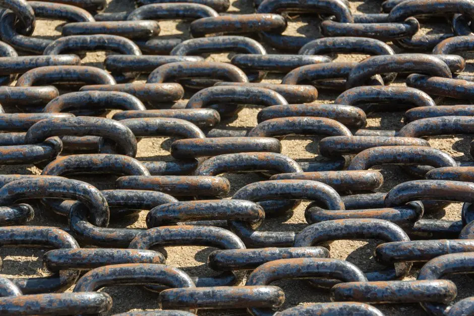
The secondary clarifier sits after the aeration basin and before disinfection or filtration, separating biological floc from treated effluent and returning activated sludge to the aeration tank as RAS (S3, S4). Because biological floc is lighter and more fragile than primary sludge, secondary SOR runs tighter at 20–30 m³/m²·day, and sidewater depth is held at 3.5–5 m to dampen hydraulic turbulence that would otherwise break floc into pin-floc washout (S4). A rising sludge blanket that exceeds the 0.3–0.9 m optimum depth is the first warning that a peak event is about to push solids over the weir (S4).
Circular units in the 15–60 m diameter range are the workhorse for square sites and high-capacity single units; the center-feed well radiates flow outward, and the rotating scraper arm pushes sludge to a central hopper. The dominant maintenance risk is the center-drive torque and automatic rake-lift, which trips when the scraper hits a compacted sludge mound (S4). Rectangular units, 3–6 m wide and up to 90 m long, suit shared-wall retrofits and multiple parallel trains; the weak point is chain-and-flight tension, sprocket wear, and the catastrophic failure mode of a snapped chain dropping flights onto the basin floor (S4).
2026 A2O field data anchors the realistic performance envelope. A 12-month municipal sampling program (Sep 2023–Sep 2024) reports secondary clarifier final effluent means of 0.22 ± 0.05 mg/L LAS, 13.18 ± 3.7 mg/L NO₃-N, and 4.46 ± 0.18 mg/L TP, with the anoxic tank identified as the primary nitrate-reduction stage and the oxic tank carrying most of the LAS and phosphorus removal (Scientific Reports, 2026-04). Operators must tune RAS during wet weather to keep the blanket stable — without that adjustment, sudden surges of solids consolidate into dense layers that force an emergency basin drop (S3, S4). For sites where the secondary clarifier is being replaced or skipped entirely, the HydropureWater MBR system consolidates clarification and membrane separation in one tank.
| Parameter | Circular Secondary | Rectangular Secondary |
|---|---|---|
| Typical size | 15–60 m diameter | 3–6 m wide, up to 90 m long |
| SOR band | 20–30 m³/m²·day | 20–30 m³/m²·day |
| Sidewater depth | 3.5–5 m | 3.5–5 m |
| Sludge blanket target | 0.3–0.9 m | 0.3–0.9 m |
| Collector mechanism | Center-drive rotating scraper arm | Chain-and-flight or traveling bridge |
| Primary maintenance risk | Drive torque, rake lift, center bearing | Chain tension, sprocket wear, flight alignment |
| Best-fit site | Square footprint, single high-capacity unit | Shared-wall retrofit, multiple parallel trains |
| Capital intensity | Medium to high (concrete + drive) | Medium (shared walls reduce concrete volume) |
Lamella and Inclined-Plate Clarifiers: When a Compact Footprint Wins
Lamella (inclined-plate) clarifiers stack parallel plates at 45–60° inside a compact basin, multiplying the projected horizontal settling area so the effective area can reach roughly 10× the basin footprint (S4). The same principle applies to tube-settler media in honeycomb form, but plates remain the standard configuration for municipal retrofits. Surface loadings of 20–40 m/h are achievable — far above a conventional SOR — and that is the entire reason these units exist: where the civil footprint is the binding constraint, lamella trades floc-quality sensitivity for a 10:1 area reduction.
The trade-off is sharp. Lamella is highly sensitive to upstream floc quality: without well-formed, dense floc from coagulation or polymer dosing, fine particles bypass the plate pack and the high surface loading becomes a washout rather than a benefit. The HydropureWater catalog reports that pairing a high-efficiency sedimentation tank with a sludge-recirculation design and an automatic polymer dosing system can cut chemical consumption by up to 30% versus older single-pass lamella designs (HydropureWater product data, 2026). Periodic acid cleaning of the plate packs is required to remove CaCO₃ and metal-hydroxide scale that otherwise reduces effective area (S4). Best fits are industrial pretreatment, metal-hydroxide precipitation, polishing duty on biological effluents, and capacity retrofits inside existing concrete basins where a conventional clarifier simply will not fit.
Dissolved Air Flotation vs Gravity Clarifier: Where DAF Wins
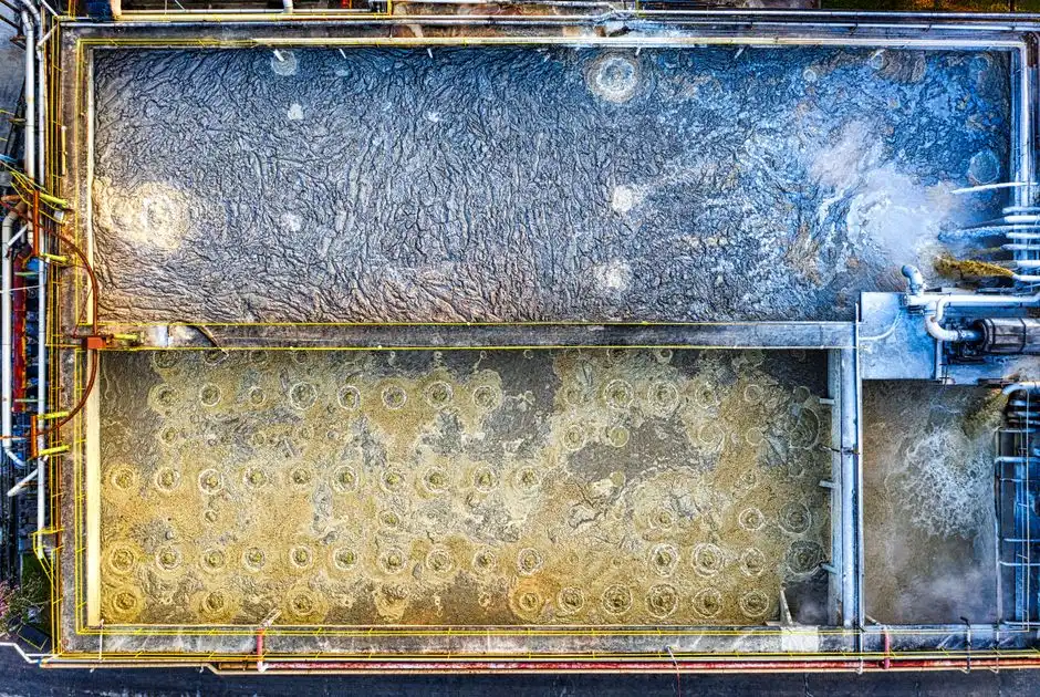
DAF works in the opposite direction of a gravity clarifier. Instead of letting particles settle, micro-bubbles (typically 10–100 µm) attach to suspended matter and float it to the surface, where a skimmer removes the floated layer. The mechanism is decisive when the target particles are too light or too colloidal to settle at a reasonable SOR — emulsified oils, free FOG, algae, and low-density biological floc that would otherwise be lost over a secondary weir.
The HydropureWater DAF product line covers 4–300 m³/h across 13 standard models and is proven in food processing, pulp & paper, textile, metalworking, petrochemical, and municipal pre-treatment duties (HydropureWater product data, 2026). DAF is the right clarifier when the influent carries high FOG or oil & grease, emulsified or colloidal solids, algae-laden pond water, or a low-density biological floc that a gravity secondary would lose. It is the wrong clarifier when the stream is high-grit and high-density inorganic — gravity settling is faster and cheaper there, and a DAF will simply load its float layer with grit that complicates skimming. The two technologies are complementary, not interchangeable, and a HydropureWater DAF system slotted ahead of a primary or secondary clarifier changes the downstream SOR, sludge density, and FOG-recovery economics in ways the master table in the next section makes explicit.
Head-to-Head Comparison: Selecting the Right Clarifier Type in 2026
The selection rule for a 2026 clarifier spec is: high raw TSS + grit → primary clarifier; biological floc + nutrient polishing → secondary circular/rectangular; footprint constraint + good upstream floc → lamella; high FOG or colloidal load → DAF. That decision rule, plus the table below, lets a process engineer pick a clarifier from the influent TSS, FOG fraction, and footprint envelope without re-deriving the design from first principles.
| Clarifier Type | Influent Stage | Typical SOR / Loading | Footprint Factor | Capital Intensity | Best-Fit Application | 2026 Watch-Out |
|---|---|---|---|---|---|---|
| Primary (rectangular or circular) | Raw sewage after screens/grit | 30–50 m³/m²·day (avg) | 1× baseline | Low to medium | High-TSS, grit-bearing raw sewage; first-stage load reduction | FOG programs shifting plants toward DAF pre-treatment |
| Secondary circular | Mixed liquor from aeration | 20–30 m³/m²·day | 1× baseline | Medium to high | Square site, single high-capacity BNR train | Blanket loss at peak wet-weather flow |
| Secondary rectangular | Mixed liquor from aeration | 20–30 m³/m²·day | 1× baseline | Medium | Shared-wall retrofits, multiple parallel trains | Chain-and-flight wear; flight drop failure mode |
| Lamella / inclined-plate | Coagulated/flocculated water | 20–40 m/h | ~0.1× baseline | Low equipment / high civil if new basin | Footprint-constrained retrofits, metal precipitation, polishing | Floc-quality sensitivity; plate scale without acid cleaning |
| DAF | High-FOG, colloidal, or algae-laden water | 5–25 m/h hydraulic, ~5–50 g/m² solids load | 0.2–0.5× baseline | Medium to high (skid + saturator) | FOG recovery, food/paper/petrochem pre-treatment, algae-laden water | Recycle pump and saturator maintenance; high energy per m³ |
The 2026 A2O numbers cited above (13.18 mg/L NO₃-N, 4.46 mg/L TP at the secondary clarifier effluent) define the realistic target a secondary clarifier must defend inside a modern BNR train. Where a plant cannot meet those targets consistently at peak flow, an MBR sidesteps the clarifier entirely; the packaged MBR plant buying guide and the packaged MBR selection guide for hot-climate sites cover that path. Wet-weather peak-flow design is the variable that breaks most 2010s-vintage specs: SOR targets must be met at peak, not just at average, and a 2026 design memo should state both numbers explicitly.
2026 Compliance, Monitoring, and Maintenance Considerations
Monitoring discipline now separates compliant clarifiers from chronic-effluent-spike clarifiers. Sludge-blanket level sensors tied to RAS pump speed have become standard in new builds because they react to a rising blanket faster than an operator reading a hand-held column can (S4). Operators should track SOR versus design continuously during events, not just totalized daily flow — a clarifier that holds its SOR envelope during a peak event will hold its permit; one that does not will spike TSS and BOD into the effluent within minutes.
Weir and launder hygiene belongs on a fixed cadence: bi-weekly brushing plus aluminum weir covers to limit algae regrowth on V-notch weirs and to control odor in primary launders (S3, S4). Drive maintenance is the dominant downtime source: torque-sensing arms and automatic rake-lift on circular units, weekly chain-tension and sprocket-tooth inspection on rectangular units, and squeegee-blade replacement once contact with the floor slope is lost (S4). Any basin drain is a confined-space entry under OSHA 29 CFR 1910.146 — air testing, ventilation, inflow isolation, and trained rescue staff are non-negotiable (S3). On the solids side, the downstream dewatering choice matters for the full mass balance; a plate-and-frame filter press sized off the clarifier underflow is the typical pairing, and a disc filter retrofit guide covers the polishing step that frequently follows secondary clarification in 2026 reuse trains.
Frequently Asked Questions
Which clarifier type is best for municipal wastewater in 2026?
There is no single winner; selection is driven by influent characteristics and site constraints. Raw sewage with high TSS and grit goes to a primary clarifier (SOR 30–50 m³/m²·day, 50–65% TSS removal); biological floc from an aeration basin goes to a secondary circular or rectangular clarifier (SOR 20–30 m³/m²·day, sidewater depth 3.5–5 m); footprint-constrained retrofits with good upstream floc use a lamella/inclined-plate clarifier (~10× the effective area in ~1/10 the footprint); and high-FOG or colloidal streams use DAF. The four families are complementary, not interchangeable.
What is the difference between a primary clarifier and a secondary clarifier?
A primary clarifier sits after screening and grit removal and removes 50–65% of TSS and 20–35% of BOD from raw sewage, handling dense, abrasive solids. A secondary clarifier sits after the aeration basin and separates lighter biological floc from treated effluent, returning activated sludge as RAS and operating at a tighter SOR (20–30 m³/m²·day) and deeper sidewater depth (3.5–5 m) to avoid breaking fragile floc. Confusing the two leads directly to mis-specification, because the solids type, loading, and required effluent quality are different at each stage.
How much smaller is a lamella clarifier than a conventional clarifier?
A lamella or inclined-plate clarifier achieves the same effective settling area as a conventional clarifier in roughly one-tenth the basin footprint, by stacking parallel plates at 45–60° to multiply the projected horizontal area. Surface loadings of 20–40 m/h are achievable — well above a conventional SOR — but the unit is highly sensitive to upstream floc quality and typically requires chemical coagulation or polymer dosing plus periodic acid cleaning of the plate packs.
When should a DAF be used instead of a gravity clarifier?
DAF is the right choice when the target particles are too light or too colloidal to settle at a reasonable SOR — high FOG or oil & grease streams, emulsified or colloidal solids, algae-laden water, and low-density biological floc that would be lost over a secondary weir. DAF is the wrong choice for high-grit, high-density inorganic streams, where gravity settling is faster and cheaper and grit loading complicates the DAF float layer.
What surface overflow rate should a secondary clarifier be designed for in 2026?
Secondary clarifiers are designed for 20–30 m³/m²·day at average flow, with sidewater depth of 3.5–5 m and a sludge-blanket target of 0.3–0.9 m. In 2026 design reviews the wet-weather peak SOR should be checked explicitly — many 2010s-vintage specs were sized at average dry-weather flow and fail at peak, which is where the blanket rises above 0.9 m and solids carry over the effluent weir.