Why a Hanoi data center treatment train is not a copy-paste from HCMC or a temperate design
A 30 MW Hanoi campus pulled out of a U.S. temperate or HCMC reference design will fail on three independent axes before the first cubic meter is treated. First, the wet-bulb envelope is different. Hanoi's dry-season design wet-bulb drops to 8-12°C in December-February, but the summer wet-bulb sits in the 26-30°C band from May to September (Vietnam Meteorological and Hydological Administration station data, 2025). That seasonal swing forces swing-feed pretreatment and an effective cycles-of-concentration ceiling of 3-5, not the 6-7 that temperate U.S. sites design around, because both the Langelier Saturation Index and the silica saturation index worsen with temperature. Second, the Red River basin source water is not the Dong Nai. TDS typically runs 100-250 mg/L, with dry-season conductivity climbing 40-60% above the July-September monsoon baseline as flow drops and agricultural drainage concentrates (MONRE Red River basin monitoring, 2024-2025). Silica sits at 5-15 mg/L seasonally, and TSS swings force antiscalant dose targets and RO recovery limits to be re-set month-to-month. Third, the permit path diverges from HCMC. Hanoi campuses typically sit in industrial parks along the Bac Ninh or Hung Yen border, discharge to a park WWTP whose inlet spec is routinely tighter than QCVN 40:2015/BTNMT Column B, and need a separate Hanoi DONRE discharge permit for any drain to the Red River, the To Lich basin, or the Nhue sub-basin. That permit path is the item that locks in pretreatment and pH-trim design, and it must be confirmed during FEED, not commissioning. Engineers who anchor the mass balance on our HCMC data center blowdown baseline will get the wet-bulb math wrong by 2-3°C and the source-water envelope wrong by a full seasonal conductivity band.
What cooling tower blowdown actually looks like in a Hanoi cooling loop
CTBD is not "concentrated makeup water" in a simple sense — it is a chemically altered stream. The evaporative process leaves behind dissolved solids while treatment chemicals added upstream to keep the loop healthy end up in the purge. Working ranges a Hanoi operator should design around: TDS 2-5x the makeup value (so 200-1,250 mg/L on a Red River feed), silica 20-80 mg/L after concentration with a soft 150 mg/L ceiling at the RO inlet to avoid calcium-silicate scaling, copper and zinc 0.1-1.0 mg/L from corrosion-inhibitor programs, total phosphorus 2-10 mg/L from phosphonate scale inhibitors, residual oxidizing biocide (chlorine or ClO2) typically 0.1-0.5 mg/L, and pH shifted to 8.0-9.0 to control the Langelier index on the loop (industry CTBD characterization data, 2025-2026). Three scaling species set the recovery ceiling — silica, calcium carbonate, and calcium sulfate — and the saturation indices for all three worsen at Hanoi's summer wet-bulb, forcing a lower local recovery than a temperate BWRO design (IDE Tech, 2026). The blowdown ratio is governed by a simple identity: blowdown fraction of makeup equals 1/(CoC − 1). At 4 CoC the fraction is 25%, at 6 CoC it drops to 20%, and in Hanoi, where the practical ceiling is 3-5 CoC, the working band is 20-33% of makeup. A 30 MW campus pulling on the order of 1-2 ML/day of makeup will see 250-500 kL/day of blowdown — enough to justify side-stream recovery but small enough that ZLD rarely pays back below 50 MW.
| Parameter | Typical Hanoi makeup (Red River) | CTBD at 4 CoC | RO concentrate ceiling (75-80% recovery) | Design driver |
|---|---|---|---|---|
| TDS (mg/L) | 100-250 | 400-1,000 | 1,600-4,000 | LSI control, RO flux |
| Silica (mg/L as SiO2) | 5-15 | 20-60 | ≤150 (soft cap) | Calcium-silicate scaling |
| Calcium hardness (mg/L as CaCO3) | 40-90 | 160-360 | 640-1,440 | CaCO3 scale, antiscalant dose |
| Total P (mg/L) | <0.05 | 2-10 | 8-40 | Phosphate fouling, nutrient load |
| Cu / Zn (mg/L) | <0.02 | 0.1-1.0 | 0.4-4.0 | QCVN heavy-metal ceiling, RO fouling |
| pH | 7.2-7.8 | 8.0-9.0 | 7.5-8.5 (post-antiscalant) | LSI control, discharge trim |
| Residual oxidizer (mg/L) | 0.3-0.8 (post-chlorination) | 0.1-0.5 | <0.1 (dechlor before RO) | Membrane oxidation damage |
Two non-obvious items deserve a callout. First, the winter cold-shock on the cooling loop when ambient drops to 8-12°C wet-bulb can swing the LSI into a corrosive regime for any plant that holds the loop at fixed alkalinity through the dry season — the chemistry setpoint needs to be seasonal, not annual. Second, the upstream antiscalant/biocide program is the single biggest determinant of blowdown treatability, and a 2026 site that runs an aggressive phosphonate program will need DAF ahead of RO, while a site on a non-oxidizing program can often drop DAF and run multi-media filtration alone. For the chemistry side, the working reference for both sizing and CIP frequency is the ClO2 cooling-loop troubleshooting baseline.
The QCVN 40:2015/BTNMT compliance anchor and the Hanoi permit path
QCVN 40:2015/BTNMT is the binding national technical regulation on industrial wastewater in Vietnam, and it is the document any Hanoi data center will be measured against. The regulation is structured in two columns: Column A applies to discharges into water bodies used as sources for domestic water supply, and Column B applies to discharges into other receiving waters. Most Hanoi industrial-park sites will discharge under Column B through a park WWTP, but the engineer should still confirm with the park operator and the provincial authority before locking any design. The 2026 limits to design around are pH 6-9 at the outlet, temperature ≤40°C at the outlet, residual chlorine controlled, oil and grease ≤10 mg/L, total nitrogen controlled to low mg/L ranges, and TDS typically required to be reported and capped by permit (QCVN 40:2015/BTNMT regulatory text). Two of these are routine failure modes for CTBD-heavy sites: temperature, because warm CTBD blends with the rest of the plant drain at 30-35°C and can spike toward the 40°C cap in summer, and pH, because the cooling loop runs at pH 8-9 to control Langelier index and blowdown inherits that pH. Engineers should plan for a pH trim step on the discharge line, not on the cooling loop, to avoid pushing the loop into a corrosive regime. If the data center is co-located with a park WWTP, the park operator typically sets an inlet acceptance specification tighter than the national Column B limits — for example, a lower TDS cap or a stricter residual chlorine limit — and that inlet spec is the binding design basis. Discharges to the Red River, the To Lich basin, or the Nhue sub-basin also require a separate Hanoi DONRE discharge permit, and the procedural path should be confirmed during FEED, not after commissioning.
The 2026 baseline process train for a Hanoi data center
The defensible 2026 baseline train is a four-stage flow with a parallel sludge line, sized for a 5-50 MW campus on Red River makeup. Stage 1 — Pretreatment: a rotary mechanical bar screen for cooling-tower intake protection takes out drift, leaves, and basin debris, then a multi-media filter ahead of the side-stream RO drops TSS to below 5 NTU, with PLC-controlled antiscalant and biocide dosing on a conductivity-triggered feed. Stage 2 — Side-stream RO or side-stream softening: two trains are realistic. Train A is a side-stream RO skid for cooling-tower makeup at 75-80% recovery, with the permeate blended back into cooling-tower makeup and the concentrate sent to the brine-management stage. Train B is sodium-cycle softening to push CoC from 4 to 6-7, which lowers blowdown from 25% to 13-14% of makeup — often the right call for 5-30 MW colocation sites where RO operating complexity is not warranted. Stage 3 — Concentrate management: RO brine is the hard stream. The upper-bound option is a fluidized-bed brine desalter at ~95% recovery followed by crystallization, but in Hanoi's 2026 capex environment this is justified only above 50 MW (IDE Tech, 2026). Below that, brine is typically sent to the industrial-park WWTP. Stage 4 — Polishing and disinfection: an MBR polishing step before discharge or on-site reuse brings TSS below 1 mg/L and reduces bacterial load, with an on-site ClO2 generator for cooling-loop microbial control sized to handle both the cooling loop and any on-site reuse line. Sludge line: a DAF for oil and suspended-solids removal handles clarifier underflow, and a plate-and-frame filter press for blowdown sludge dewatering produces a 25-30% dry-solids cake for off-site disposal; wet sludge volume is typically 0.3-0.8% of treated flow.
| Stage | Unit operation | Function | Typical sizing for 30 MW |
|---|---|---|---|
| 1. Intake & pretreatment | Bar screen + multi-media filter + DAF | Debris removal, TSS <5 NTU, oil removal | 50-200 m³/h, PLC-controlled |
| 2. Side-stream RO or softening | BWRO 75-80% recovery OR Na-cycle softener | Permeate to cooling makeup; CoC push 4 → 6-7 | 30-150 m³/h permeate (RO); 2-3 m³ resin (softener) |
| 3. Concentrate management | Park WWTP discharge OR brine desalter + crystallizer | Brine routing or near-ZLD | 10-50 m³/h brine to WWTP; ZLD only >50 MW |
| 4. Polishing & disinfection | MBR + ClO2 generator | TSS <1 mg/L, microbial control | 30-150 m³/h, on-site ClO2 at 1-5 kg/h |
| Sludge line | Lamella + plate-and-frame press | Thickening, 25-30% DS cake | 0.3-0.8% of treated flow as wet sludge |
Two sizing notes for the FEED scope. First, the antiscalant and biocide dosing point sits between Stage 1 and Stage 2, and the dosing logic should be conductivity-triggered, not flow-paced, because the Red River swings conductivity 40-60% seasonally. Second, the discharge pH trim sits at the outlet of Stage 4, not on the cooling loop, to keep the loop in a controlled LSI band of 0.0-0.5 across both winter and summer operating regimes. For a cold-climate swing-feed comparison, the Stockholm data center blowdown reference covers winter cold-shock design, and the Barcelona data center blowdown reference covers a Mediterranean water-stress context with a similar side-stream RO architecture.
Four treatment options for a Hanoi campus, mapped to site size and permit risk
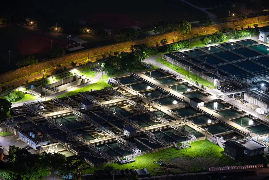
Most Hanoi data centers will choose between four realistic trains, and the choice is driven as much by site size and discharge permit risk as by capex. Option A — Treat and discharge: pretreatment plus a DAF or high-efficiency sedimentation tank to meet QCVN Column B, then sewer. Lowest capex, but highest ongoing water-and-discharge cost and the highest permit risk if the receiving WWTP tightens its acceptance spec. Option B — Side-stream RO reuse: pretreatment plus a side-stream RO skid at 75-80% recovery feeding cooling-tower makeup, with brine routed to the industrial-park WWTP. Mid capex, 30-50% net freshwater reduction on a 30 MW campus; the 15 MW benchmark in the Genesis Water 2026 analysis recovered 60% (3 MGD/yr) of blowdown at a 6.7-year base payback narrowing to 3-5 years once avoided costs are priced in. Option C — Softening plus closed-loop cooling: push CoC from 4 to 6-7 with sodium-cycle softening, drop blowdown from 25% to 13-14% of makeup, no RO needed. Lowest operating complexity, best fit for 5-30 MW colocation where operator headcount is constrained. Option D — Full zero liquid discharge: RO plus brine desalter at ~95% recovery plus crystallizer. High capex, justified only above 50 MW and where land and discharge are genuinely constrained. For a 5-30 MW colocation site on Red River makeup, Option C is the dominant choice on operating complexity, with Option B layered in once the campus crosses ~15 MW and the operator has dedicated water staff. For sizing the DAF inside Options A and B, the DAF design parameters guide is the working reference.
| Option | Recovery / CoC | Best-fit site size | Capex band (2026 USD) | Permit risk | Operating complexity |
|---|---|---|---|---|---|
| A — Treat and discharge (DAF + sewer) | No reuse; CoC unchanged at 3-4 | <5 MW, strong sewer access | Low six figures | High | Low |
| B — Side-stream RO reuse | 75-80% RO recovery; 30-50% net freshwater reduction | 15-50 MW | Mid six to low seven figures | Medium | Medium (membrane CIP, antiscalant) |
| C — Softening + closed loop | CoC 4 → 6-7; blowdown 25% → 13-14% | 5-30 MW colocation | Mid six figures | Low | Low (salt regeneration) |
| D — Full ZLD (RO + desalter + crystallizer) | ~95% (near-zero liquid discharge) | >50 MW, constrained discharge | High six to low seven figures; 2-5x Option B delta at 30 MW | Very low | High (crystallizer, brine chemistry) |
Capex is presented as bands, not a price list, because the Hanoi 2026 EPC market has more variance in civil works and resin/membrane freight than in equipment. As a working anchor: Option A sits in the low six figures USD for a 5 MW site; Option B in the mid six to low seven figures for a 15-30 MW site; Option C in the mid six figures for a 5-30 MW site; Option D in the high six to low seven figures and rising sharply with crystallizer scope. Payback on Option B sits at 6.7 years base case for the 15 MW benchmark, narrowing to 3-5 years once permit-risk reduction, ESG reporting value, and avoided freshwater tariff inflation are priced in. The Hanoi-specific economic twist mirrors HCMC: freshwater tariffs and discharge fees are materially lower than at arid U.S. sites, so the business case leans less on direct water-cost savings and more on permit certainty, ESG and FDI-investor reporting, and the water-stress narrative that international hyperscale tenants increasingly require in RFPs. Engineers building the financial model should put explicit line items on "avoided permit risk" and "ESG/外资 reporting value" rather than relying on water-tariff arbitrage alone. A permit-and-monitoring checklist to lift into the FEED scope: (1) confirm QCVN 40:2015/BTNMT Column A vs Column B with the park operator in writing; (2) obtain the park WWTP inlet acceptance spec and treat it as the binding design basis; (3) confirm Hanoi DONRE discharge permit scope (Red River, To Lich, Nhue); (4) install online conductivity, pH, temperature, and residual chlorine on the discharge line; (5) schedule monthly composite sampling for TDS, TN, TP, heavy metals per the permit schedule; (6) pre-approve the antiscalant and biocide chemistry with the park operator before commissioning, not after.
Frequently Asked Questions
What QCVN limits drive the design of a Hanoi data center's CTBD train?
The binding parameters are pH 6-9 at the outlet, temperature ≤40°C at the outlet, oil and grease ≤10 mg/L, residual chlorine controlled, total nitrogen in the low mg/L range, and TDS reported and capped by permit (QCVN 40:2015/BTNMT). Temperature and pH are the two routine failure modes for CTBD-heavy sites because the cooling loop runs at pH 8-9 and 30-35°C.
What cycles-of-concentration ceiling should a Hanoi engineer design around?
The effective ceiling is 3-5 CoC, not the 6-7 typical of temperate U.S. sites, because Hanoi's summer wet-bulb in the 26-30°C band worsens both the Langelier Saturation Index and the silica scaling index. At 4 CoC the blowdown fraction is 25% of makeup; at 3 CoC it is 33%.
Is ZLD justified for a 30 MW Hanoi campus?
Generally no below 50 MW. The capex delta between side-stream RO and full ZLD is on the order of 2-5x for a 30 MW campus, the crystallizer pulls significant power and operator attention, and Vietnam's industrial-park WWTP network is currently willing to accept brine within an inlet spec. ZLD becomes defensible above ~50 MW or where the site has a specific discharge-zero permit constraint from the provincial authority.
Which option is the right baseline for a 5-30 MW colocation in Hanoi?
Option C — sodium-cycle softening plus a closed-loop push from 4 to 6-7 CoC, with the modest blowdown sent to the park WWTP. It delivers the lowest operating complexity, fits the operator headcount typical of colocation, and avoids the membrane-CIP burden of side-stream RO.
What payback should a 2026 Hanoi feasibility study show for side-stream RO?
Expect 4-6 years on a 30 MW campus once permit risk, ESG reporting value, and freshwater-tariff inflation are priced in. The base-case calculation (water-cost-only) on the 15 MW benchmark sits at 6.7 years, narrowing to 3-5 years with full avoided-cost accounting. Hanoi's lower water tariffs push the simple payback longer than at an arid U.S. site, so the business case should be built on total cost of ownership and non-financial value rather than water-cost savings alone.