Why textile effluent breaks a conventional activated sludge plant
Textile dye-house wastewater typically carries COD of 800–3,000 mg/L, color bodies from reactive, disperse, vat, and azo dye classes, and a pH that swings between 4 and 11 across batch dumps, all at temperatures from 30 to 60 °C. Conventional activated sludge (CAS) clears about 83% of COD and 66% of TSS in those conditions, and essentially none of the color; reactive azo and anthraquinone chromophores pass through the aeration basin largely intact because biological breakdown of those aromatics is the rate-limiting step, not air supply. The secondary clarifier compounds the problem: dye toxicity and high F/M ratios trigger bulking sludge, and the clarifier overflows with pin floc and unsettled solids on every shift change.
Four pain points show up in every plant manager's monthly review: color non-compliance with the local regulator, recurring sludge bulking events that knock the clarifier offline, a clarifier footprint that consumes land the mill cannot spare, and an effluent that is too dirty to send back to a dye bath. The UPC thesis work (S4) ran CAS, MBR, and MBBR side by side on the same textile feed and confirmed MBR beat CAS on every metric tested: 91% COD, 99.4% TSS, and 80% color at a 1.3-day HRT, against CAS's 83% COD and 66% TSS. If your existing CAS line is failing on any of the four pain points above, the BOD removal engineering guide shows why biology alone is no longer the bottleneck — the separator is.
What an MBR actually does inside a textile plant
An MBR couples a conventional activated-sludge basin with a submerged microfiltration or ultrafiltration membrane module that replaces the secondary clarifier entirely. In a textile duty the membrane is normally 0.03–0.1 µm PVDF hollow fiber, 0.1 µm PVDF flat sheet, or a 0.1 µm ceramic element; pore size is well below the 1–5 µm threshold a clarifier can settle, so biomass, colloids, and most dye macromolecules are physically rejected rather than left to gravity. The two-stage logic is simple: biology degrades dissolved organics, then the membrane delivers a near-sterile, low-turbidity effluent independent of sludge settleability.
Four operating parameters govern performance, and the 2026 RSM study on aerobic ceramic MBRs (AeCeMBR, S1) lists them explicitly: hydraulic retention time (HRT), organic loading rate (OLR), mixed liquor suspended solids (MLSS), and transmembrane pressure (TMP). HRT sets the contact time biology gets; OLR sets the food-to-microbe ratio; MLSS is the biomass concentration inside the basin; TMP is the suction-side pressure that drives permeate through the membrane and is the primary fouling indicator. Holding MLSS at 8,000–12,000 mg/L, roughly 2–3× a CAS basin, is what lets the MBR absorb shock loads from dye batches while shrinking the basin footprint by 50–60% compared to a clarifier-equipped line.
MBR performance on textile wastewater: the real numbers
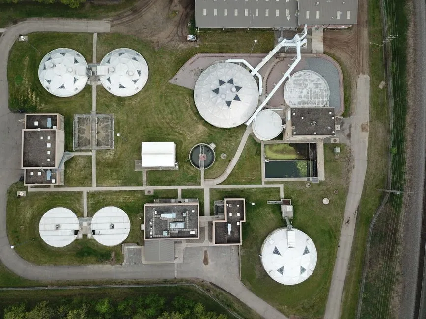
Standalone submerged MBR on real textile feed delivers 91% COD, 99.4% TSS, and 80% color removal at a 1.3-day HRT (S4, UPC pilot). The 2026 aerobic ceramic MBR study (AeCeMBR, S1, Membranes) pushed both COD and turbidity removal to approximately 96% across 174 experimental points, with a Box-Behnken RSM model fit of R² > 0.95 and validation errors under 2%; a random forest model coupled with Monte Carlo simulation confirmed the same result at R² = 0.92 (COD) and R² = 0.97 (turbidity). The hybrid MBBR-MBR configuration — biofilm carriers ahead of the membrane — hit 93% COD, 85% color, and 99% TSS at a 1-day HRT, and the treated water was reused directly into new dye baths with color differences DE_CMC(2:1) < 1, inside the textile industry's general acceptance band (S4).
Color removal is the textile plant's number-one pain point, and the headline 80–85% figure hides a critical disaggregation. Reactive azo and anthraquinone dyes are the hardest to strip biologically — the chromophore survives the aeration tank and shows up in MBR permeate as residual color in the 50–200 ADMI range, which fails reuse and tight discharge limits. Disperse and vat dyes are easier because they partition onto biomass and are rejected with the sludge, but they bleed back into the supernatant if the sludge is not wasted properly. A 2025–2026 pilot retrofit with flat-sheet PVDF modules (S3, Membranes) confirmed lab-scale numbers carry over to brownfield textile plants, and that an MBR alone rarely meets reuse color spec without an ozone, Fenton, or RO polish step downstream.
| Configuration | COD removal | TSS removal | Color removal | HRT | Source |
|---|---|---|---|---|---|
| Submerged MBR (PVDF) | 91% | 99.4% | 80% | 1.3 d | S4 (UPC) |
| Aerobic ceramic MBR (AeCeMBR) | ~96% | ~96% turbidity | n/r | optimized | S1 (Membranes 2026) |
| MBBR-MBR hybrid | 93% | 99% | 85% | 1 d | S4 (UPC) |
| Flat-sheet MBR retrofit (pilot) | lab → field confirmed | >99% | 75–85% | 1–1.5 d | S3 (Membranes, 2025–2026) |
| Conventional activated sludge (baseline) | 83% | 66% | limited | 2 d | S4 (UPC) |
Hollow-fiber vs flat-sheet vs ceramic MBR for textile duty
Three membrane formats dominate the real textile MBR market, and the right choice depends on influent temperature, footprint, retrofit constraints, and cleaning aggressiveness, not on a single removal-percentage number. Hollow-fiber submerged MBRs use 0.03–0.1 µm PVDF fibers in bundles, deliver the highest packing density and the lowest capex per m², and are the workhorse in Chinese and Indian textile parks — but they are sensitive to hair and fiber fouling without a rotary bar screen in front. Flat-sheet MBRs use 0.1 µm PVDF panels (the DF series is a common commercial example) that are individually replaceable, sit above an integrated aeration box that scours the membrane with coarse bubbles, and run at 10–20× lower energy than external cross-flow designs, which is why they dominate containerized and brownfield retrofits. Ceramic MBRs use 0.1 µm Al₂O₃ or TiO₂ elements, tolerate high MLSS, aggressive NaOCl and acid cleaning, and dye-house liquor at 40–60 °C; the 2026 AeCeMBR pilots (S1) show 96% COD removal with long service life, at a higher first cost than polymeric formats.
The trade-off is straightforward: ceramic wins on robustness and membrane life; flat-sheet wins on retrofit ergonomics and operating cost; hollow-fiber wins on first cost and packing density. For greenfield low-cost textile parks the hollow-fiber DF-style module is the default; for a brownfield retrofit where the existing aeration tank must host the membrane cassette, DF-series flat-sheet MBR modules are the practical answer; for high-temperature liquor, aggressive chemical cleaning, or a plant that wants a 10-year membrane replacement interval, ceramic is the right call. A packaged integrated MBR system ships with the membrane rack, blowers, permeate pumps, and PLC pre-wired, which is what most EPC contractors specify for textile mill retrofits.
| Format | Pore / material | Strength | Weakness | Best fit |
|---|---|---|---|---|
| Hollow-fiber submerged | 0.03–0.1 µm PVDF | Lowest capex per m², highest packing density | Sensitive to fiber/hair fouling | Greenfield, large textile parks |
| Flat-sheet submerged | 0.1 µm PVDF (e.g. DF series) | Replaceable elements, low energy, easy retrofit | Lower packing density than hollow-fiber | Brownfield retrofits, containerized plants |
| Ceramic submerged | 0.1 µm Al₂O₃ / TiO₂ | High-temp, aggressive CIP, long life | Higher capex, heavier modules | High-temp dye liquor, harsh chemistry |
Pretreatment and post-treatment: the train around the MBR
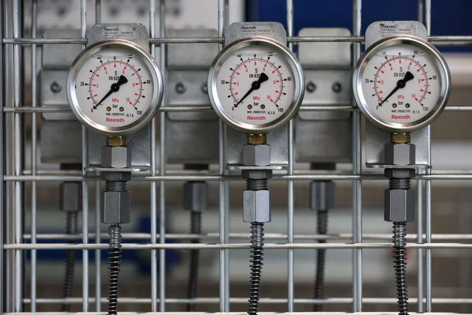
An MBR without equalization and pre-screening will foul in three months; this is the most common reason textile MBR retrofits fail. Dye-house batch dumps swing pH 4–11 and temperature 30–60 °C, both of which destabilize biology and accelerate membrane fouling, so an equalization basin with pH correction to 6.5–7.5 is non-negotiable. A rotary bar screen at 2–3 mm protects the membrane from fibers and lint, and DAF pre-treatment ahead of the MBR strips suspended solids and a meaningful fraction of color, which cuts MBR organic loading and reduces coagulant demand downstream.
Post-treatment is dictated by the discharge or reuse target. For discharge-only, an optional ozone or Fenton polish can lift color above 95% removal, and the trade-offs of each advanced oxidation step are mapped in the Fenton oxidation guide. For reuse, MBR effluent typically feeds UF followed by RO, with a permeate conductivity under 200 µS/cm and color below 5 ADMI, suitable for rinse-water and even some dye-bath make-up. Sludge handling is the last step: MBR retentate is concentrated activated sludge at 1–2% dry solids, and a plate-and-frame filter press is the standard dewatering unit for textile plants, producing a cake above 25% DS that can go to landfill or, where permitted, to a cement kiln.
Fouling control and operating window on textile MBRs
Textile MBRs foul faster than municipal MBRs because dye chemistry, surfactants, and sizing agents deposit on the membrane as a gel layer. The AeCeMBR study (S1) gives the operating window: hold MLSS at 8,000–12,000 mg/L, alarm on TMP at 20–30 kPa, and run continuous coarse-bubble aeration under the membrane cassette for scouring. A relaxation cycle of 9 minutes on, 1 minute off is the standard flux-maintenance routine and is more effective than backwash for textile feeds because it lets the gel layer diffuse away rather than driving it deeper into the pore.
Chemical clean-in-place (CIP) is needed every 2–4 weeks on textile duty, against every 6–12 weeks on municipal. The standard recipe is 500–1,000 mg/L NaOCl for organic fouling followed by 1–2% citric acid for inorganic scaling; never mix them in the same CIP loop. TMP, flux, and MLSS should be logged on a PLC with SCADA trending, and the alarm thresholds should fire before irreversible fouling sets in. The predictive maintenance guide shows how to wire TMP rate-of-change into a work-order trigger so CIP happens on condition rather than on a calendar. Backwash water and CIP reject must be routed back to the equalization tank, never into the MBR basin, and the same SCADA stack that drives work orders can be configured for multi-site reporting via the SaaS wastewater management platform guide.
2026 cost, footprint, and ROI for a textile MBR
The headline number for a CFO is footprint and reuse. HydropureWater's integrated MBR systems run 10–2,000 m³/day and cut basin footprint by approximately 60% versus a CAS line of the same treatment capacity, mainly because the secondary clarifier disappears and MLSS doubles (HydropureWater product data, 2026). The flat-sheet DF module range produces 32–135 m³/day per cassette at 80–225 m² of membrane area, which is the right granularity to size a 500 m³/day dye-house line at four to five modules with one redundant for CIP rotation.
CAPEX is the line item a CFO will challenge, and the UPC industrial-scale model (S4) is the most defensible data point: an MBBR-MBR hybrid saved 68.4% of CAPEX versus an MBR-alone configuration, with comparable OPEX, and delivered an internal rate of return (IRR) of 18%. The reuse economics usually dominate the ROI case: closing the loop on dye-rinse water cuts fresh-water intake, reduces effluent discharge tax, and in many jurisdictions unlashes water-reuse subsidies. For a deeper breakdown of CAPEX/OPEX per cubic meter across MBR configurations, the MBR cost per m³ guide gives 2025–2026 bandings.
| Driver | CAS (baseline) | Submerged MBR | MBBR-MBR hybrid | Aerobic ceramic MBR |
|---|---|---|---|---|
| Footprint vs CAS | 1.0× | ~0.4× | ~0.5× | ~0.4× |
| HRT (textile) | 2 d | 1.3 d | 1 d | 0.8–1.2 d (optimized) |
| CAPEX vs MBR-alone | +68.4% (S4) | baseline | −68.4% (S4) | higher first cost |
| Reuse-ready effluent | no | with RO polish | yes (DE_CMC(2:1) < 1, S4) | yes, with RO polish |
| Typical flow range | any | 10–2,000 m³/d | 10–2,000 m³/d | 10–2,000 m³/d |
How to specify an MBR for a textile plant in five steps
Step 1 — characterize the influent. Pull a week of composite samples and run COD, BOD₅, color (ADMI and Pt-Co), pH, temperature, TDS, and a dye-class split (reactive vs disperse vs vat vs azo). The dye-class split drives whether you need a polish step for reuse.
Step 2 — set the effluent target. If discharge-only, your local regulator's COD, BOD, TSS, color, and TDS limits define the MBR envelope. If reuse, the spec is tighter: color typically below 5–20 ADMI, conductivity under 200–500 µS/cm depending on the dye class, and that almost always means an RO polish downstream.
Step 3 — pick the membrane format. Hollow-fiber PVDF for greenfield, low-first-cost installations; flat-sheet DF for brownfield retrofits and containerized plants; ceramic for high-temperature dye liquor or plants that want aggressive chemical cleaning and 10-year membrane life.
Step 4 — design the pre- and post-train. Equalization with pH and temperature dampening → rotary bar screen → DAF for color and SS stripping → MBR → optional UF/RO polish for reuse → disinfection. Size equalization for at least 8–12 hours of hydraulic residence to flatten batch swings.
Step 5 — plan O&M upfront. Define TMP alarm thresholds (20–30 kPa), CIP cadence (every 2–4 weeks for textile duty), sludge dewatering with a plate-and-frame filter press, and stock at least one replacement membrane cassette per format on site to avoid 8-week shipping delays on a fouled batch.
Frequently Asked Questions
What COD and color removal can an MBR achieve on textile wastewater?
A submerged PVDF MBR typically removes 91% COD, 99.4% TSS, and 80% color at a 1.3-day HRT (S4, UPC pilot). The 2026 aerobic ceramic MBR study reports approximately 96% COD and turbidity removal with R² > 0.95 and validation errors under 2% (S1, Membranes 2026). A hybrid MBBR-MBR reaches 93% COD and 85% color at a 1-day HRT (S4).
What hydraulic retention time does a textile MBR need?
Submerged PVDF MBRs on textile feed run at 1.3 days HRT; MBBR-MBR hybrids run at 1 day; AeCeMBR pilots optimize in the 0.8–1.2 day range (S1, S4). Below 0.8 days biology cannot complete color and COD removal on reactive azo feeds, and TMP rises sharply.
Ceramic vs polymeric MBR for textile duty — which is better?
Ceramic (0.1 µm Al₂O₃/TiO₂) handles higher temperatures, more aggressive CIP, and longer membrane life; the 2026 AeCeMBR pilot reports 96% COD removal (S1). Polymeric PVDF hollow-fiber or flat-sheet modules cost less up front and are easier to retrofit; flat-sheet DF cassettes are individually replaceable, which suits brownfield textile plants. Pick ceramic for high-temp liquor and 10-year membrane life, flat-sheet for retrofits, hollow-fiber for greenfield low-first-cost.
Can MBR effluent be reused directly in new dye baths?
MBBR-MBR hybrid effluent was reused directly into new dyeings with color differences DE_CMC(2:1) < 1, inside the textile industry's acceptance band (S4). For most reuse cases an RO polish after the MBR is needed to drop conductivity below 200 µS/cm and color below 5 ADMI; that combination is what closes the loop on dye-rinse water and drives most of the ROI on textile MBR retrofits.
How often does a textile MBR need chemical cleaning?
Textile MBRs foul faster than municipal MBRs because of dye and surfactant loading, and CIP with 500–1,000 mg/L NaOCl followed by 1–2% citric acid is typically needed every 2–4 weeks versus every 6–12 weeks on municipal duty (S1, S3). Set TMP alarm at 20–30 kPa and trigger CIP on rate-of-change rather than a fixed calendar to catch fouling before it becomes irreversible.