Why a Copenhagen Data Center Is a Different Water Problem
The 22.5 MW atNorth DEN01 facility in Copenhagen routes its full waste-heat output through HOFOR's district-heating network, heating roughly 8,000 homes — and that single design choice is what separates Nordic data-center water engineering from every generic hyperscale water guide on the web (mGrid, 2026-02). When condenser heat is a product rather than a waste, the cooling loop runs above the 25–30 °C return set point typical of a non-heat-exporting site, which accelerates silica polymerization and shifts the saturation index for calcium carbonate upward. A site that exports heat cannot push cycles of concentration (CoC) by chemistry alone; the loop temperature ceiling is set by the district-heating contract, not by the operator's comfort with scaling risk.
Copenhagen's cool climate partially compensates. Average wet-bulb temperatures run 10–14 °C through most of the year, so evaporative loss per kW of heat rejected is materially lower than at equivalent sites in Frankfurt or Dublin. Even so, the heat-recovery contract dictates a minimum loop temperature, which limits how far a site can lean on atmospheric cooling before falling back on mechanical assistance. For perspective on raw demand: IDE Tech's 2026 figures indicate that a 100 MW facility can require up to 2 million L/day of make-up water. Scaling that linearly to a 22.5 MW site puts a typical Nordic data center in the 400,000–500,000 L/day range under standard operating load — a number that anchors the water balance worked through below.
The Three Wastewater Streams a Copenhagen Site Has to Manage
"Data center wastewater" is not a single stream, and treating it as one is the most common engineering shortcut that produces non-compliant discharge. A Copenhagen facility runs three hydraulically separate streams, each with its own chemistry, its own permit path, and its own reuse potential.
Stream 1 — Cooling tower blowdown (CTBD). The largest by volume and the highest-value reuse target. CTBD is enriched in silica (commonly 20–80 mg/L as SiO2 after concentration), calcium, magnesium, hardness, residual antiscalant, and biocide residues, and it leaves the cooling loop warm (IDE Tech, 2026). It is brackish, scale-prone, and the stream any high-recovery design must address first.
Stream 2 — Process and condensate wastewater. Humidification bleed-off, chiller blowdown, air-side economizer condensate, and RO concentrate (if RO is present on the make-up side). Volumes are lower than CTBD, temperatures are warmer, and there may be trace glycol from chilled-water loops. This stream is normally treated or routed internally rather than discharged to sewer.
Stream 3 — Sanitary and facility wastewater. Black and grey water from offices, welfare areas, cafeterias, and any on-site accommodation. This stream is conventional domestic-strength wastewater and must meet standard Miljøstyrelsen discharge parameters to the municipal sewer; it has no direct interaction with the cooling chemistry.
The 20–40% of intake water that leaves as blowdown at a typical 4 CoC operating point is the volume opportunity most sites underuse (Genesis Water Tech, 2026). CTBD is already conditioned, already at temperature, and already on site — converting it from a disposal cost into a reuse resource is the single largest lever available to a Nordic facility.
| Stream | Typical % of total wastewater | Key contaminants | Default destination |
|---|---|---|---|
| Cooling tower blowdown (CTBD) | 70–85% | Silica, Ca, Mg, hardness, biocides, antiscalants | Treatment → reuse as make-up |
| Process / condensate | 10–20% | Low TDS, possible glycol traces, warm | Internal reuse or sewer (with permit) |
| Sanitary / facility | 5–10% | BOD, TSS, nutrients (domestic profile) | Municipal sewer per Miljøstyrelsen permit |
Copenhagen Water Balance for a 22.5 MW Site: Intake, Evaporation, Blowdown
Working from the IDE Tech 100 MW = 2,000,000 L/day benchmark, a 22.5 MW Nordic site drawing evaporative cooling under typical operating load will intake on the order of 450,000 L/day of fresh make-up water (IDE Tech, 2026). That figure assumes a moderate wet-bulb climate and a PUE around 1.2–1.3 — a Danish heat-exporting site typically lands there because the heat-recovery contract discourages over-cooling.
The CoC math is the next step. At 4 CoC, blowdown equals 1/(CoC − 1) = 25% of make-up, which gives roughly 110,000 L/day of CTBD for the 22.5 MW site. Push to 6 CoC and blowdown drops to 20%, freeing approximately 22,000 L/day of make-up that would otherwise have been drawn, treated, and discharged (Genesis Water Tech, 2026). That 5-percentage-point reduction is a 20% relative cut in blowdown volume — not the 50% many sustainability leads assume when they hear "move from 4 to 6 CoC."
WUE framing helps, but only up to a point. Industry figures for data center WUE sit at 0.47–0.65 gal (1.8–2.5 L) per kWh (Genesis Water Tech, 2026). The metric obscures the difference between consumption (water permanently lost to evaporation or product incorporation) and usage (water withdrawn, used, and returned to the watershed). A site that recycles 60% of its blowdown reports the same WUE as one that dumps it — only a mass balance separated into consumption versus discharge reveals the real efficiency. Evaporative loss is the only water permanently removed from the local watershed; the design goal is therefore to minimize both evaporation (via the heat-recovery tie-in that lowers rejected heat per kW) and blowdown (via higher CoC plus reuse).
| Parameter | At 4 CoC | At 6 CoC |
|---|---|---|
| Daily make-up (L/day) | ~450,000 | ~428,000 |
| Daily blowdown (L/day) | ~112,500 (25%) | ~85,700 (20%) |
| Daily evaporation (L/day) | ~337,500 | ~342,300 |
| Annual blowdown volume (m³/yr) | ~41,000 | ~31,300 |
| Blowdown reduction vs. 4 CoC | — | ~9,800 m³/yr (≈ 24%) |
Regulatory Frame: Miljøstyrelsen, EU IED, and the District-Heating Contract
Three overlapping instruments govern what a Copenhagen facility can discharge, reuse, and contractually export. The first is the Miljøbeskyttelsesloven (Danish Environmental Protection Act) administered by Miljøstyrelsen, with sewer discharge permits issued via HOFOR or the relevant municipal wastewater utility. Typical sewer limits for industrial discharger permits in the Copenhagen region include pH 6.5–9.0, temperature ≤ 35 °C to sewer, suspended solids typically < 250–500 mg/L (case-specific), hydrocarbons, and metals screening. CTBD that has been pre-treated for hardness removal and metals usually clears these; CTBD that has not will not.
The second instrument is EU Industrial Emissions Directive 2010/75/EU (IED). It applies to a data center only if the site has on-site combustion above 50 MWth — most commonly backup diesel generators, gas-fired peaking, or combined heat and power tied to the heat-recovery contract. The relevant BREF documents are the Waste Treatment BREF (for any on-site wastewater treatment plant above threshold) and the LCP BREF (Large Combustion Plant, for backup generation). For a Nordic site where the heat-recovery contract is the load-following partner, the threshold may be approached via CHP rather than backup generation.
The third instrument is the HOFOR district-heating supply contract itself. It sets the return-temperature and pressure window for the condenser loop, and any change in cooling-loop chemistry (higher CoC, different antiscalant, alternative corrosion inhibitor) must not push the loop outside the contractually agreed heat-transfer envelope. Finally, for any make-up water that re-enters the cooling loop in contact with air, the drikkevandsbekendtgørelsen (Danish drinking water order) and EU Drinking Water Directive 2020/2184 govern aerosol and indirect-contact risk.
| Instrument | Applies to | Key obligation for a Copenhagen data center |
|---|---|---|
| Miljøbeskyttelsesloven / Miljøstyrelsen permit | All discharge to municipal sewer | pH 6.5–9, T ≤ 35 °C, TSS, hydrocarbons, metals screening |
| EU IED 2010/75/EU + Waste Treatment BREF | On-site WWTP above IED thresholds | BAT conclusions for biological treatment if sanitary stream treated on-site |
| EU IED 2010/75/EU + LCP BREF | On-site combustion > 50 MWth (backup / CHP) | ELV monitoring, stack emissions, operating windows |
| HOFOR district-heating contract | Heat-recovery tie-in | Return-temperature and pressure window; chemistry compatibility |
| Drikkevandsbekendtgørelsen / EU DWD 2020/2184 | Make-up water contacting air in cooling loop | Aerosol and indirect-contact risk management |
Cooling Tower Blowdown Chemistry: Why Conventional RO Stalls at 75–80% Recovery
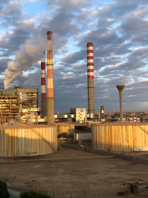
CTBD from a Nordic, heat-exporting site is a brackish stream that has been concentrated by evaporation. Typical composition sits at 20–80 mg/L silica as SiO2, elevated calcium and bicarbonate, sulfate from any sulfuric-acid-based pH control, and the residuals of the antiscalant and biocide program already in the loop (IDE Tech, 2026). The first membrane that sees this stream is a conventional brackish-water RO (BWRO), and that membrane hits its scaling threshold quickly.
Conventional BWRO typically plateaus at 75–80% recovery on a CTBD feed; beyond that point, chemical consumption rises, fouling accelerates, and clean-in-place frequency becomes uneconomic (IDE Tech, 2026). The constraint is not osmotic — it is the saturation limit of the sparingly soluble salts. Calcium carbonate and silica are the first to breach; calcium sulfate follows when the recovery curve pushes sulfate concentration past its solubility product.
Higher CoC operation amplifies the problem. Genesis Water Tech notes that biological and scaling risks increase exponentially above 5–6 CoC without advanced treatment, which is why most operators who try to push CoC on chemistry alone end up rolling it back when asset damage appears (Genesis Water Tech, 2026). Any high-recovery system that targets the 90–95% range on CTBD therefore has to solve three challenges simultaneously: decouple salt removal from the osmotic ceiling, control scaling chemistry proactively rather than defensively, and hold stable single-stage operation without interstage boosting.
The High-Recovery Treatment Train: Pretreatment, RO, and Closed-Loop Brine Handling
The train that gets CTBD to 90–95% overall recovery is a four-stage system, with a sidestream polish bolted to the cooling loop itself. Pretreatment comes first: a multi-media filter dropping SDI below 3, followed by a UF pretreatment skid ahead of the RO with 0.03 µm PVDF membranes rated to accept up to 300 ppm turbidity. UF removes colloids, microbiological carryover, and any oil traces that would otherwise foul the RO.
Stage 2 is the primary RO at conservative recovery — typically ≤ 70% — sized as an industrial RO unit at conservative recovery. The permeate is already suitable for cooling-tower make-up and is the main reuse product. The concentrate is not sent onward as brine in the conventional sense; it is routed to a controlled-precipitation reactor (a fluidized-bed contactor) where antiscalant carryover is intentionally deactivated and silica, CaCO3, and CaSO4 precipitate onto seed material. The dense solids are withdrawn as a filterable pellet — a solid waste stream, not a sludge. After this stage, the remaining liquor is essentially NaCl and can be sent to a secondary dynamic-RO stage for 90–95% overall system recovery. The MAXH2O case study reports ~95% recovery with permeate silica at ~1 mg/L on a comparable industrial feed (IDE Tech, 2026).
The sidestream polish keeps the main cooling loop at 5–6 CoC without inviting scaling: low-flow side-stream filtration, antiscalant and dispersant dosing calibrated for the higher silica and CaCO3 load, and biocide control that does not leave persistent organics accumulating in the circulating water. The sanitary stream is handled separately by a packaged MBR for the sanitary/facility stream, which produces an effluent that meets local discharge standards independent of cooling-loop chemistry. For a comparative Nordic perspective, the tropical-climate counterpart guide for Rio de Janeiro addresses very different ambient wet-bulb and discharge-temperature constraints but the same three-stream logic applies; readers scoping multi-region portfolios can cross-reference the Rio counterpart guide for the heat-rejection differences.
Right-Sizing for Copenhagen: 22.5 MW Hyperscale vs. 2–10 MW Colocation

Not every site can carry hyperscale CAPEX. The full high-recovery train — UF, primary RO, controlled-precipitation brine stage, and secondary dynamic RO — pays back only when the daily volume justifies the operator expertise and the chemical consumables. The 22.5 MW atNorth DEN01-class site sits comfortably in the hyperscale tier: 450,000+ L/day of make-up, 60–80% blowdown reuse, and an in-house water treatment specialist or a service contract that provides one.
Mid-market colocation (5–15 MW) usually deploys multi-media filtration plus side-stream UF and a targeted chemical program to push CoC from 4 to 6. The blowdown reduction is real — about 5 percentage points, or ~20% relative — and a partial-reuse skid sized 100–300 GPM covers toilet flushing, irrigation, and washdown without the CAPEX of full RO on CTBD (Genesis Water Tech, 2026). The 5 MW facility that tries to install a hyperscale water-reuse package typically drives CAPEX per gallon treated 3–4× higher than a hyperscale site and finds the system sitting idle or running badly because the operator headcount is not there (Genesis Water Tech, 2026).
Edge and small colocation (≤ 5 MW) usually means a modular physical-treatment skid at 100–300 GPM, no RO on blowdown, and reuse limited to non-critical applications where local rules allow. For a high-altitude or tropical comparison where the chemistry drivers differ, the high-altitude counterpart guide for La Paz and the Brasília counterpart guide show the same right-sizing principle applied to different ambient and regulatory envelopes.
| Site scale | Recommended train | Realistic blowdown reuse | CAPEX intensity |
|---|---|---|---|
| Hyperscale (≥ 20 MW) | MMF + UF + primary RO + controlled-precipitation brine stage + secondary dynamic RO + side-stream polish | 60–80% (to cooling make-up) | Baseline |
| Mid-market colo (5–15 MW) | MMF + side-stream UF + targeted chemistry; partial-reuse skid for non-critical reuse | 15–25% (to non-critical uses) | ~50–60% of hyperscale per m³ |
| Edge / small colo (≤ 5 MW) | Modular physical-treatment skid 100–300 GPM, no RO | Local-rule-permitted reuse only | ~25–35% of hyperscale per m³ |
Frequently Asked Questions
How much cooling water does a Copenhagen data center use?
Working from the IDE Tech 2026 benchmark of 100 MW = 2,000,000 L/day of make-up, a 22.5 MW Nordic site under typical operating conditions draws on the order of 450,000 L/day. Of that, roughly 110,000 L/day becomes cooling tower blowdown at 4 CoC, and roughly 337,000 L/day is lost to evaporation — the only water permanently removed from the local watershed (IDE Tech, 2026).
Can cooling tower blowdown be reused as cooling-tower make-up?
Yes, with the right train. UF + primary RO at ≤ 70% recovery already produces permeate suitable for cooling-tower make-up. For high overall recovery (~95%), add a controlled-precipitation / closed-loop brine stage that withdraws silica, CaCO3, and CaSO4 as dense solids and routes the remaining NaCl-rich liquor to a secondary dynamic-RO stage. IDE Tech's MAXH2O case reports ~95% recovery with permeate silica at ~1 mg/L (IDE Tech, 2026).
What regulates Copenhagen data center water discharge?
Discharge to municipal sewer is governed by Miljøstyrelsen permits under the Miljøbeskyttelsesloven, with sewer-specific limits set by HOFOR or the relevant utility (typical: pH 6.5–9, temperature ≤ 35 °C, TSS, hydrocarbons, metals). On-site combustion above 50 MWth — typically backup generation or CHP — triggers EU Industrial Emissions Directive 2010/75/EU and the LCP BREF. Any on-site wastewater treatment plant above the IED threshold follows the Waste Treatment BREF.
Does the district-heating tie-in change the water treatment?
Yes. Exporting condenser heat to HOFOR's network keeps loop temperatures above the 25–30 °C return set point of a non-heat-exporting site, which accelerates silica polymerization and shifts the CaCO3 saturation index upward. That re-rates the antiscalant program, tightens CoC control, and is the single biggest reason a conventional BWRO cannot push past 75–80% recovery on this stream (IDE Tech, 2026; mGrid, 2026-02).
Is on-site wastewater treatment required?
Only for the sanitary/facility stream, which must meet domestic discharge parameters to municipal sewer and is typically handled by a packaged MBR. Cooling-loop streams (CTBD, process/condensate) are not sewage and are normally treated and recycled on site, with brine residuals withdrawn as a solid waste stream or, where permitted, discharged under the industrial discharge permit rather than the domestic one.
Related Equipment
- industrial RO unit at conservative recovery — specifications, capacity range, and technical data
- packaged MBR for the sanitary/facility stream — specifications, capacity range, and technical data