Why Data Center 'Wastewater' Mostly Means Inlet Water, Not Outlet
Wastewater handling at a hyperscale data center centers on turning non-potable source water into cooling-tower make-up and managing the small blowdown stream the cooling loop rejects. Across its fleet, Google has built on-site treatment plants that pull from industrial canals, municipal wastewater sidestreams, and harvested rainwater, then meter cooling-tower blowdown back to the local sewer only when capacity allows (per datacenters.google and DataCenterKnowledge, 2010). For a 15 MW site, daily cooling demand can reach 360,000 gallons; hyperscale facilities routinely exceed 100 MW, and aggregate U.S. data-center cooling demand continues to climb as AI training loads scale up (per The Conversation, 2025-11).
Water intensity remains high due to straightforward thermodynamics. Evaporative cooling cuts data-center energy use by roughly 10% compared with air cooling in equivalent climates (per blog.google, 2026-03). That 10% translates directly into operating-cost savings and lower carbon intensity, which is why hyperscalers do not default to air-cooled designs. The trade-off is four distinct water streams a plant engineer must balance: make-up water entering the site, evaporation loss from the cooling tower, blowdown (or bleed) carrying dissolved solids out of the loop, and the occasional process drainage from humidification or equipment wash.
Most published commentary frames data-center water as a "discharge problem," but the real pinch point is the inlet. A 15 MW facility at 4–6 cycles of concentration needs a continuous supply of low-turbidity, biologically stable water, and municipal potable water is increasingly restricted in stressed watersheds. The blowdown stream, by contrast, is small in volume but high in total dissolved solids (TDS), chlorides, silica, and treatment chemicals—which is why the discharge path, not the inlet, is where permits and sewer capacity become the limiting constraint. Understanding that inversion is the first step to designing a data-center water system that survives a 2026 permitting review.
The Three Real Recycling Approaches Google Uses on Site
Google has documented three on-site recycling patterns, each matched to a different local water-stress condition. These engineering choices follow the local watershed (per DataCenterKnowledge, 2010).
1. Canal sourcing — Saint-Ghislain, Belgium. Google's Belgian facility draws raw water from the Nimy Blaton canal and routes it through a 20,000 sq ft on-site treatment plant. The plant removes sediment, recycles the separated sludge, doses biocide to control microbial growth, and pumps the finished water underground to the cooling towers. The site avoids municipal potable water entirely.
2. Municipal sidestream — unnamed U.S. site. A "sidestream" facility taps the treated effluent of an adjacent county wastewater plant, polishes it to cooling-tower spec, and returns clean water back to a public waterway through a separate effluent plant. Discharge to the local sewer is queued and batched because the sewer is near capacity.
3. Rainwater retention — second U.S. site. Site landscaping funnels stormwater into two retention ponds. A treatment plant processes the harvested water, supplying 40–100% of site demand depending on season.
The design intent across all three is to hit the company's target of using recycled water for up to 80% of total data-center consumption, while reducing dependence on stressed municipal supplies (per DataCenterKnowledge, 2010). Saint-Ghislain trades higher capital cost for complete independence from municipal water. The U.S. sidestream site accepts the constraint of having to negotiate metered discharge with the local sewer authority. The rainwater site accepts seasonal variability in exchange for near-zero withdrawal from surface or groundwater.
| Site | Source water | Treatment steps | Discharge path | Key trade-off |
|---|---|---|---|---|
| Saint-Ghislain, Belgium | Nimy Blaton canal (surface) | Sediment removal, sludge recycle, biocide dosing | None to municipal sewer; closed-loop blowdown handling | High capital cost; full independence from potable supply |
| U.S. sidestream site | County wastewater plant effluent | Sidestream polishing, separate effluent plant | Queued/batched release to near-capacity sewer | Depends on local sewer capacity and POTW cooperation |
| U.S. rainwater site | On-site retention ponds | Physical/chemical polishing for cooling spec | Minimal; surplus to landscape or pond overflow | Seasonal variability (40–100% of demand) |
The source dictates the treatment train requirements. A canal or river source demands heavy sediment and microbial control, a sidestream source demands polishing for residual organics and nutrients, and a rainwater source demands storage volume and seasonal over-design.
Inside the Treatment Train: Sediment, Microbes, and Cycles of Concentration
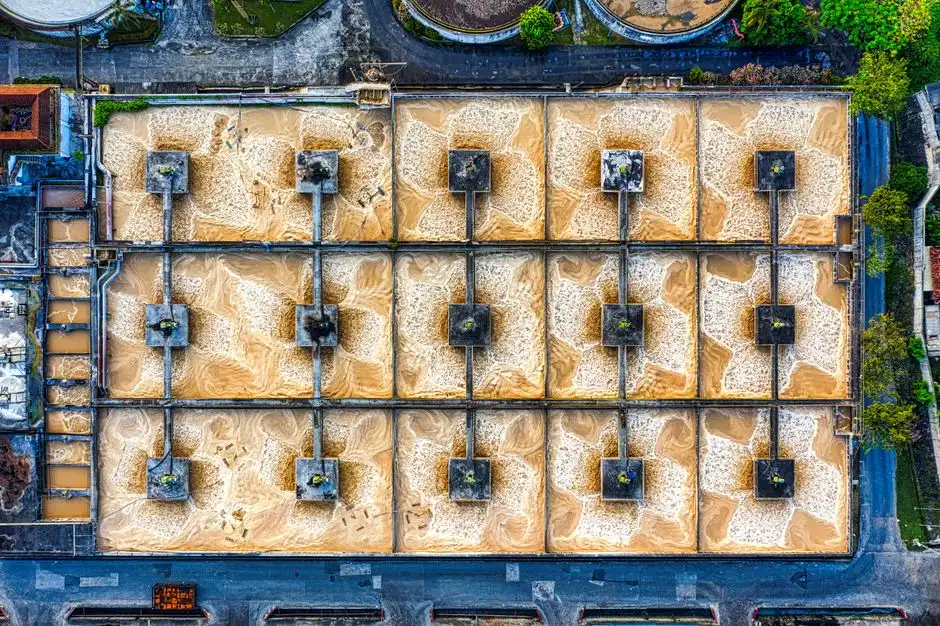
The equipment list for Google's plants is conventional, consisting of well-engineered multi-barrier trains sized to the source water.
Sediment and turbidity removal come first. Coarse screening protects downstream pumps, lamella or plate settlers drop out the bulk of suspended solids, and multi-media filtration for raw cooling make-up water polishes to the turbidity level the cooling tower can tolerate without fouling the fill. Backwash from the multi-media stage becomes a small sludge stream that is thickened and dewatered on site rather than sent to the sewer.
Microbial control runs in parallel. Cooling towers are ideal habitats for Legionella, biofilm, and sulfate-reducing bacteria, and a hyperscaler cannot afford a positive Legionella test in a closed loop. The standard tool is an on-site chlorine dioxide generator for cooling-loop microbial control, which delivers a broad-spectrum oxidant that does not break down to trihalomethanes the way chlorine does and is effective across the 6.5–8.5 pH range typical of cooling water. Dosing is metered to a residual setpoint and trimmed by online ORP.
The chemistry that governs blowdown volume is cycles of concentration (CoC)—the ratio of dissolved solids in the circulating water to dissolved solids in the make-up. Most cooling towers operate at 4–6 CoC; pushing past 6 invites calcium carbonate and silica scaling, while pulling back to 3 inflates blowdown volume. The plant engineer's primary lever is a PLC-controlled chemical dosing system for cycles of concentration control that holds CoC at the maximum the source chemistry allows. This envelope is identical for an industrial cooling loop at a refinery, a steel mill, or a data center, making blowdown treatment a standard scope item on most 2026 cooling-water retrofits.
What Happens to the Blowdown — and Why Municipal Sewers Are the Real Bottleneck
Cooling-tower blowdown is small in volume compared with the make-up stream, but it carries the concentrated chemistry the tower has been evaporating for weeks. Total dissolved solids routinely run 2,000–4,000 mg/L, chlorides can exceed 500 mg/L, silica climbs toward 150 mg/L, and treatment-chemical residuals (bromide, phosphate, polymer) are part of the mix. Discharging that to a sewer designed for domestic waste is the failure mode Google engineers around—and it is the same failure mode industrial plants face in water-stressed regions.
Google's response is operational: "queuing and batching" blowdown to a near-capacity municipal sewer, releasing it only when the treatment plant has hydraulic headroom (per DataCenterKnowledge, 2010). That works when you have storage equalization, a willing POTW, and time. It does not work when the local authority imposes strict TDS, chloride, or silica limits—which is increasingly the case under 2026 U.S. NPDES pretreatment rules and EU discharge frameworks.
Where sewer capacity is genuinely constrained, the answer is on-site blowdown polishing. A side-stream industrial RO system for blowdown polishing can recover 70–85% of the blowdown as reusable cooling make-up, with the reject routed to a high-efficiency sedimentation tank for solids drop-out before final disposal. That is a second treatment train documented Google sites do not yet use, but which the next generation of hyperscale plants in Phoenix, Madrid, and the U.A.E. will almost certainly need.
Lessons a 2026 Industrial Buyer Can Borrow From Google's Playbook

Google's data centers document the failures as well as the wins, including sewer-capacity problems, seasonal rainwater shortfalls, and permit negotiations. Four principles transfer to an industrial cooling-water or process-water project in 2026:
- Site water risk first, technology second. Run a science-based watershed assessment before selecting air vs water cooling. If the watershed is stressed, air cooling, hybrid cooling, or a recycled-water source should be on the table.
- Specify multi-barrier treatment trains sized for the source, not for the discharge. Sediment removal, mechanical bar screening at the intake, multi-media filtration, and on-site chlorine dioxide generation cover roughly 90% of the routine operating risk.
- Design the discharge path on day one. Confirm sewer capacity, NPDES/POTW limits, and the likely need for blowdown polishing before locking in cycles of concentration. The cheapest time to add an RO polish train is during the original design, not after the first permit violation.
- Build replenishment into the project plan. Google's replenishment program has scaled to 165+ projects across 97 watersheds, with annual investment rising from $17 million to $77 million (per blog.google, 2026-03). Permit and ESG conversations on a 2026 industrial site are easier when a replenishment line is already on the page.
Water sourcing and water discharge are not separate scopes; they are the same scope viewed from two ends of a cooling loop.
Frequently Asked Questions
How does Google treat wastewater at its data center plant?
Google treats wastewater at its data centers by reusing non-potable source water on site for cooling rather than treating sewage for discharge. At Saint-Ghislain in Belgium, a 20,000 sq ft plant cleans canal water for the cooling towers; at one U.S. site a sidestream facility polishes effluent from a county wastewater plant; at another U.S. site, retention ponds supply 40–100% of demand from harvested rainwater. The goal is to source up to 80% of total data-center water from recycled supplies (per DataCenterKnowledge, 2010).
What does Google do with cooling tower blowdown?
Cooling-tower blowdown is metered back to the local sewer only when capacity allows, a practice Google calls "queuing and batching." At the U.S. sidestream site where the municipal sewer is near capacity, the plant negotiates discharge windows with the POTW. Where sewer capacity is constrained further, the next step is on-site blowdown polishing, typically via reverse osmosis followed by sedimentation of the reject stream (per DataCenterKnowledge, 2010).
How much water does a hyperscale data center use per day?
A 15 MW data center can use up to 360,000 gallons of water per day for cooling; hyperscale facilities above 100 MW scale that proportionally, and AI-driven workloads are pushing totals higher in 2026. Water cooling cuts data-center energy use by roughly 10% versus air cooling in equivalent climates, which is why the water demand persists even as efficiency improves (per blog.google, 2026-03, and DataCenterKnowledge, 2010).
Can industrial cooling plants use the same on-site recycling approach as Google?
Yes, the operational envelope is identical. Any industrial cooling loop operates at 4–6 cycles of concentration, faces the same silica and chloride limits on blowdown, and benefits from the same multi-barrier treatment train: screening, sedimentation, multi-media filtration, and on-site biocide generation. For examples of how this is being applied to specific regional sites, see the case studies on data center cooling blowdown treatment in Rosario and