Why Soft Drink Wastewater Needs More Than a Standard Filter
Raw soft drink effluent arrives at the treatment plant with COD of 6,900–7,500 mg/L, TDS of 900–1,800 mg/L, and turbidity of 2,000–3,000 NTU (Namaghi & Mousavi, 2014, J. Taiwan Inst. Chem. Eng.). That profile reflects dissolved sugars, color bodies, syrup carryover, and cleaning chemicals, and it rules out simple cartridge or sand filtration on its own. A membrane step is required either to polish biologically treated effluent or to act as the primary separation on raw influent when surfactants are dosed upstream.
A 2024 peer-reviewed study on biologically treated soft drink wastewater used a modified polyethersulfone (PES) ultrafiltration (UF) membrane and reported effluent COD of 13 mg/L and turbidity of 2 NTU (Moradi, Zinatizadeh & Zinadini, 2024, Water Environ. Res. 96(2):e10997). That is the working benchmark a beverage plant engineer should be writing into a polishing spec. The 2014 MEUF study on raw soft drink influent (COD 6,900–7,500 mg/L) demonstrated effective COD and TDS rejection using an SDS/TX-100 mixed-surfactant system at 3 bar TMP (Namaghi & Mousavi, 2014), giving an alternative configuration when biological treatment is not feasible.
Process Train: Where UF Fits in a 2026 Beverage Effluent Plant
A 2026 commercial process train for a soft drink bottler typically looks like this: screening and equalization → dissolved air flotation (DAF) for suspended solids and FOG → biological treatment (conventional activated sludge or membrane bioreactor) → UF polishing → RO for water reuse. Each step has a defined job. Screening protects downstream equipment. Equalization buffers the batch discharges from CIP cycles. DAF removes the bulk of floatables, oils, and settleable solids before they load the biology. Biological treatment breaks down dissolved sugars and BOD. UF then takes the biologically clarified water and strips residual colloids, biomass carryover, and high-molecular-weight organics down to a turbidity and SDI suitable for RO. RO then produces reuse-quality water for rinsing, boiler feed, or cleaning.
For plants with a tight footprint, the submerged MBR with integrated UF combines the biological reactor and the physical separation step in a single tank; products in this class are typically rated at <1 µm equivalent filtration with capacities in the 10–2,000 m³/day range (see submerged MBR with integrated UF and the upstream DAF unit for FOG and TSS reduction). The downstream 0.03 µm PVDF hollow-fiber UF system is then positioned as RO pretreatment, not a stand-alone reuse barrier.
| Step | Primary function | Typical placement |
|---|---|---|
| Screening / equalization | Remove gross solids; buffer batch flow | Head of works |
| DAF | Remove FOG, suspended solids, floatables | Pre-biological |
| Biological (CAS or MBR) | Degrade dissolved sugars and BOD | Before UF |
| UF (0.03 µm PVDF) | Polish colloids, turbidity, SDI; protect RO | Post-biological, pre-RO |
| RO | Produce reuse-quality permeate | Final reuse barrier |
How UF Works on Soft Drink Effluent: Pore Size, Material, Flux
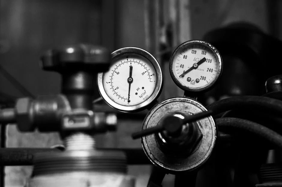
Ultrafiltration is a pressure-driven membrane process with a nominal pore size of 0.01–0.1 µm that retains colloids, bacteria, and high-molecular-weight organics while passing water and low-molecular-weight solutes (per the Moradi et al. 2024 characterization framework). For beverage effluent polishing, 0.03 µm PVDF hollow fiber is the working specification: it balances reliable turbidity and SDI reduction with manageable transmembrane pressure, and the PVDF chemistry tolerates the caustic and acid cleaning cycles a sugary effluent demands.
Material choice matters. The 2024 Moradi study used PES as the base polymer and improved fouling resistance by blending in 0.5 wt% BM-TA-GQD nanoparticles; AFM mean roughness fell from 2.07 nm (bare PES) to 0.84 nm (modified PES), and the flux recovery ratio rose from 44.58% to 71.35% (Moradi et al., 2024). Translated into commercial practice: smoother, more hydrophilic membrane surfaces resist organic fouling better and extend the interval between chemical cleans. Industrial systems in this duty are commonly packaged in 2,000–40,000 L/h capacities (per the 0.03 µm PVDF hollow-fiber UF system product range).
| Parameter | Working value | Source |
|---|---|---|
| Nominal pore size | 0.01–0.1 µm; 0.03 µm typical for RO pretreatment | Moradi et al., 2024 |
| Membrane material | PVDF (industrial default); PES (academic, modifiable) | Moradi et al., 2024 |
| Mean roughness (Sa) | 2.07 nm bare PES → 0.84 nm with 0.5 wt% BM-TA-GQD | Moradi et al., 2024 |
| Flux recovery ratio | 44.58% (bare) → 71.35% (modified) | Moradi et al., 2024 |
| Effluent COD (polishing) | 13 mg/L | Moradi et al., 2024 |
| Effluent turbidity (polishing) | 2 NTU | Moradi et al., 2024 |
Operating Envelope: TMP, Flux, Backwash, and Air Scour
The 2014 Namaghi & Mousavi MEUF study identified 3 bar as the transmembrane pressure (TMP) at which the maximum rejection of COD and TDS was achieved on raw soft drink influent; in commercial effluent polishing, however, industrial hollow-fiber UF typically operates at a much lower 0.5–2.0 bar TMP, since the feed has already been biologically stabilized and the membrane is sized for sustainable flux rather than maximum rejection. The same study documented a characteristic flux profile: high initial flux, with measurable decline inside the first 4 hours of operation as the fouling layer builds (Namaghi & Mousavi, 2014). That early decline is normal and is reversed by routine maintenance, not chemical cleaning.
Routine maintenance on an industrial UF skid is automatic. A backwash cycle, triggered either by elapsed time or by a differential-pressure setpoint across the membrane module, reverses flow through the fibers to dislodge the fouling layer. Air scour — coarse bubble aeration in the membrane tank during the backwash — provides mechanical agitation that improves solids removal from the fiber surface. Both cycles are PLC-controlled and restore flux without a chemical clean. Chemical cleaning (CIP) is run on a longer interval using the same reagents cited in the 2014 MEUF methodology: sodium hydroxide for organic fouling and hydrochloric acid for scale and metal oxides (Namaghi & Mousavi, 2014). Valves, instruments, and media for the cleaning loop are standardized components (see water treatment parts, valves, and media).
UF vs MEUF vs MBR+UF: Choosing the Right Membrane Step
Standalone UF is the simplest configuration: no chemical dosing, PLC-driven backwash and air scour, and the feed turbidity is typically capped at ≤300 ppm in commercial product specifications. It works best as a polishing step on already biologically treated effluent, where its job is to deliver RO-grade SDI and protect the downstream RO from colloidal fouling. MBR with integrated UF takes the same UF membrane and submerges it directly inside the aeration tank, combining biological degradation and physical separation in one vessel; the trade is a smaller footprint and higher mixed-liquor suspended solids against higher aeration demand and more sensitive membrane cleaning. The dedicated MBR membrane bioreactor module is the consumable element that gets replaced on a multi-year cycle.
MEUF (micellar-enhanced ultrafiltration) is a different configuration: surfactants are dosed into the raw wastewater above their critical micelle concentration so that dissolved organics and metals solubilize into micelles large enough to be rejected by the UF membrane. The 2014 Namaghi & Mousavi study used SDS (CMC 8.15 mM) and TX-100 (CMC 0.25 mM) and demonstrated effective COD and TDS rejection on raw soft drink influent at 3 bar TMP, with rejection improving at higher TX-100/SDS molar ratios (Namaghi & Mousavi, 2014). MEUF is attractive when biological treatment is impractical, but it adds surfactant cost and a downstream surfactant-recovery step. A 2022 critical review benchmarked a 60,000 m³/day seawater MEUF-vs-RO plant at approximately US$0.91 per cubic meter of treated water (cited in the 2022 J. Water Process Eng. review) — a directional data point only, not a beverage-specific number.
| Configuration | Best feed | Rejection profile | Main trade-off |
|---|---|---|---|
| Standalone UF | Biologically treated effluent, ≤300 ppm turbidity | Colloids, biomass, high-MW organics | Limited on dissolved organics alone |
| MBR + UF (submerged) | Raw effluent (inside aeration tank) | BOD removal + colloidal polishing | Higher aeration energy; CIP-sensitive |
| MEUF | Raw influent with SDS/TX-100 dosing | Dissolved COD and TDS via micelle rejection | Surfactant cost and recovery |
Fouling Control: What 2024 Research Confirms Works
Two findings from the 2024 Moradi study translate directly into fouling-control practice. First, adding 0.5 wt% BM-TA-GQD nanoparticles to a PES UF membrane raised the flux recovery ratio from 44.58% to 71.35% and reduced the AFM mean roughness from 2.07 nm to 0.84 nm (Moradi et al., 2024). Second, the same modified membrane showed lower turbidity in permeated wastewater than the unmodified membrane when challenged with biologically treated soft drink effluent, consistent with both reduced fouling and antibacterial activity on the membrane surface. The operative principle is straightforward: smoother, more hydrophilic membrane surfaces resist organic deposition, and the deposited layer that does form is easier to remove during backwash.
In an operating plant, that academic finding maps onto a small number of routine controls. Consistent automatic backwash, triggered by either time or differential pressure, is the primary fouling countermeasure. Air scour during the backwash cycle provides the mechanical shear that keeps the fiber surface clean. Stable feed-side pressure prevents over-compaction of the fouling layer. Avoiding shock loads of oils, surfactants, and undissolved sugar — the operational discipline that protects both the biology upstream and the membrane downstream — keeps the cleaning interval predictable. Replacement membranes and elements for routine change-out are specified in the RO and UF membrane consumables line.
2026 Specification Checklist for a Soft Drink Wastewater UF
The following spec lines can be pasted into a 2026 RFQ for a soft drink wastewater UF system, drawn from the operating envelope and product parameters cited above. Membrane and configuration: 0.03 µm PVDF hollow fiber, outside-in flow, with a stated clean-water flux and design flux at the operating TMP. Capacity envelope: 2,000–40,000 L/h as the working range, sized to the peak shift discharge, not the average daily flow. Feed tolerance: up to 300 ppm turbidity, with a stated SDI₅ target (commonly ≤3) at the UF outlet to protect the downstream RO. Automation: PLC-controlled automatic backwash and air scour, differential-pressure trigger, data logging of TMP, flux, and cycle counts. Cleaning-in-place: dedicated CIP connections, materials compatible with caustic (NaOH) and acid (HCl) cleaning per the reagent set documented in the 2014 Namaghi & Mousavi study. Materials of construction: stainless-steel or fiber-reinforced plastic skid, food-grade piping where the permeate is destined for reuse. Spares: replacement UF elements specified for the installed module geometry, available from the replacement UF membrane elements line; the parent 0.03 µm PVDF hollow-fiber UF system for the main skid.
| Spec line | Write into the RFQ as |
|---|---|
| Membrane | 0.03 µm PVDF hollow fiber, outside-in |
| Capacity | 2,000–40,000 L/h, sized to peak shift discharge |
| Feed turbidity | ≤300 ppm; UF outlet SDI₅ ≤3 for RO protection |
| Operating TMP | 0.5–2.0 bar (industrial effluent polishing) |
| Maintenance | PLC automatic backwash + air scour, ΔP-triggered |
| CIP | NaOH and HCl compatible, dedicated CIP connections |
| Spares | Replacement UF elements matched to installed modules |
Frequently Asked Questions
What pore size and membrane material are typical for an ultrafiltration system for soft drink wastewater?
The working specification is 0.03 µm PVDF hollow fiber for industrial effluent polishing, with operating TMP in the 0.5–2.0 bar range. Academic studies such as Moradi et al. (2024) used PES as the base polymer and improved fouling resistance by blending in hydrophilic nanoparticles, but PVDF remains the commercial default for beverage effluent.
What effluent quality can a UF polishing step deliver on biologically treated soft drink wastewater?
The 2024 Moradi et al. study reported UF permeate at COD 13 mg/L and turbidity 2 NTU on biologically treated soft drink wastewater using a 0.5 wt% BM-TA-GQD/PES membrane. That effluent quality is suitable as RO pretreatment in a water-reuse train.
How does MEUF differ from a standalone UF system for soft drink wastewater?
Standalone UF is a polishing step on already biologically treated effluent and relies on physical size exclusion at the membrane pore. MEUF doses surfactants — typically SDS (CMC 8.15 mM) and TX-100 (CMC 0.25 mM) per the 2014 Namaghi & Mousavi study — above their critical micelle concentration so that dissolved organics partition into micelles large enough to be rejected by the UF membrane. MEUF can treat raw soft drink influent directly but adds surfactant dosing and recovery costs.
Why is UF placed upstream of RO in a beverage wastewater reuse train?
UF reduces the turbidity and SDI of biologically treated effluent to levels the RO membranes can tolerate. Without UF in front, RO elements foul rapidly on colloidal and biological carryover, raising operating cost and shortening membrane life. In a 2026 reuse train, UF is the SDI-reduction step; RO is the dissolved-solids rejection step.