
Why midstream oily and produced water breaks a plain clarifier
Midstream oily and produced water at a 50,000-bbl/d gathering system carries an influent envelope that no plain clarifier was designed to handle: total dissolved solids of 50,000–200,000 mg/L, oil concentrations of 200–2,000 mg/L, dissolved H₂S in the 50–500 mg/L range, paraffin and wax precipitating through the winter envelope, and intermittent proppant carry-over from flowback events (HydropureWater field data, 2026). Within that envelope, the contaminant that decides the technology choice is droplet size. Free oil above 150 µm separates by gravity in minutes inside a skim tank or API vessel; the problem is what comes out of the heater treater and chemical program — chemically treated, shear-stabilized emulsions that push droplet size below 20–50 µm, where Stokes' law makes a quiescent clarifier tank impractical. A high-TDS brine narrows the density difference between oil and water from the textbook 0.85 g/cm³ toward 0.99 g/cm³, and any paraffin film at the drop surface further slows rise velocity.
This is why the same oily stream delivers roughly 95% FOG removal in a dissolved air flotation system and only about 70% in a conventional clarifier (Ecologix 2026 selection guide). On the TSS side, refinery and petrochemical data show the same pattern: high COD, soap oil and grease, turbidity, and TSS are the typical influent envelope a midstream plant must handle, with DAF pulling emulsified oil and fine solids that gravity leaves behind (DUT study, 2022). The right question for an operator whose skim tank keeps overflowing is therefore not "clarifier or DAF" in the abstract — it is "where in the train does gravity still work, and where do I need bubble-aided flotation."
How a DAF and a clarifier actually separate oil and solids
A conventional clarifier is a quiescent tank fitted with lamella plates or tube settlers at 55–60° to accelerate gravity separation. Sludge rakes or scrapers move settled solids to a central hopper; clarified water overflows peripheral launders. It is effective on high-density grit, scale, and free-oil droplets above roughly 150 µm, and it does that work with long hydraulic retention time (typically 2–4 hours), a large footprint on the order of 5–10 m² per m³/h, and a continuous dilute-sludge underflow that drives downstream OPEX. Polymer demand is low if influent is predictable.
A dissolved air flotation unit works on a different physical principle. Pressurized recycle water — typically 10–30% of throughput, saturated at 4–6 bar — is mixed with the influent in the contact zone. When the pressure is released, micro-bubbles in the 10–100 µm range nucleate on oil droplets and fine solids, lifting them in minutes to a surface float that a top skimmer removes. The clarified subnatant exits the bottom of the cell. The two design levers a process engineer must specify are the recycle ratio and the air-to-solids ratio: recycle is normally 10–30% and A/S falls in the 0.02–0.10 range for oily wastewater, with both confirmed by jar testing on the actual midstream feed (HydropureWater design basis, 2026). The float itself is concentrated — typically 2–5% dry solids — and is easily routed to a slop-oil tank or to a dewatering press, while clarifier underflow sits at 0.5–1.5% and consumes filter-press capacity.
Chemistry separates the two technologies operationally as well as physically. DAF tolerates and usually requires a coagulant plus flocculant program — an automatic polymer and coagulant dosing skid sized to the recycle and influent load — and performance collapses if the dose drifts. A clarifier is more forgiving day-to-day but pays for that in HRT, footprint, and sludge volume. The mechanism contrast is the foundation for every parameter table and decision rule that follows.
Head-to-head on FOG and TSS at a midstream facility
The single most defensible piece of evidence for the FOG comparison is the Ecologix 2026 selection guide: on the same oily stream a dissolved air flotation system removed about 95% of FOG while a clarifier removed about 70% (Ecologix 2026, example values). On TSS, the same source shows a clarifier delivering about 90% solids reduction in a high-sediment mining case — a useful analogue for sand-dominated midstream streams — but that figure drops sharply when particle size falls below 50 µm, which is exactly the envelope DAF is built for. The table below ties the choice to the actual midstream operating envelope, with the 95% and 70% figures flagged as example/comparator values and final numbers confirmed by site-specific jar testing.
| Parameter | Dissolved Air Flotation (DAF) | Conventional Clarifier |
|---|---|---|
| FOG removal on oily midstream stream (200–2,000 mg/L inlet) | ~90–95% (Ecologix 2026 example, 95%) | ~60–70% (Ecologix 2026 example, 70%) |
| TSS removal on fine particles (<50 µm) | 80–95% | 20–50% (collapses on emulsified TSS) |
| TSS removal on coarse sand and scale | Poor — sand must be removed upstream | 85–95% (Ecologix 2026 example, 90%) |
| Sensitivity to emulsified oil (droplets <50 µm) | Low — designed for this range | High — Stokes' law dominates |
| Sensitivity to high TDS / salinity (50,000–200,000 mg/L) | Low — bubble attachment unaffected | High — oil/water density delta collapses |
| Hydraulic retention time | 20–40 minutes | 2–4 hours |
| Footprint per m³/h | 0.1–0.3 m² | 0.5–1.5 m² (lamella) up to 5–10 m² (conventional) |
| Skim / sludge handling | Concentrated float, 2–5% dry solids | Dilute underflow, 0.5–1.5% dry solids |
| Polymer / coagulant demand | Required, jar-test-driven | Optional, low dose |
| Primary OPEX driver | Compressed air + polymer | Sludge pumping + rake maintenance |
| Performance in cold weather (winter pad operations) | Recycle water must be kept >5 °C; enclosure common | Viscosity rise hurts; large basins prone to surface icing |
Two non-FOG limits need to be on the table before the operator writes a basis-of-design memo. First, DAF does not remove dissolved organics — it is primary treatment, not a replacement for biological or membrane polishing when COD/BOD is the permit driver. Second, neither technology removes dissolved salts; produced water bound for Class II injection will still need a disposal well regardless of which separation technology is upstream.
When a clarifier still wins at a midstream site
A DAF unit does not earn its place on every midstream pad. Sand, scale, and iron sulfide loadings above roughly 200 mg/L will overload a DAF cell because micro-bubbles cannot lift dense grit. In that case a clarifier, desander, or hydrocyclone must precede flotation — the Ecologix selection guide cites a mining facility with heavy sediment loads reaching 90% solids reduction with a clarifier at lower cost, which is the right analogue for any sand-dominated produced-water stream. Operators with very large flow rates and low oil-in-water — typical of saltwater disposal (SWD) injection-plant intakes where inlet oil is already below 50 mg/L after the gathering-system FWKO — often find that CAPEX per m³/h and simple gravity operation dominate the decision, with DAF reserved for downstream polish if reuse is in scope.
Two more scenarios belong on the clarifier side of the ledger. Sites without compressed-air infrastructure, or where operations cannot run a chemical program consistently, will struggle to keep a DAF unit in spec; a lamella clarifier needs less day-to-day chemistry. Greenfield sites with cheap land, long equalization basins, and no winter-freeze constraint can run gravity at HRT that a DAF simply cannot match. In all of these cases the clarifier is either the primary stage or a robust pre-DAF guard, and a packaged HydropureWater lamella clarifier can be specified as a Stage 1 sand-cutoff unit ahead of a downstream DAF.
The typical midstream treatment train: API or Wemco, then DAF, then polish
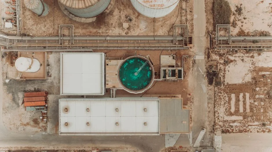
The configuration your EPC will actually draw on the P&ID is rarely "DAF or clarifier" alone. It is a four-stage train that matches each unit to the contaminant it removes best. Stage 1 is the production separator or free-water knock-out (FWKO) for bulk gas, oil, and water split at the tank battery. Stage 2 is an API separator with corrugated-plate interceptors, a Wemco induced-gas flotation cell, or both, taking free oil down toward 100 mg/L and cutting sand at the same time. Stage 3 is a DAF unit that polishes emulsified FOG to a directionally reusable envelope (FOG below 10–25 mg/L, TSS below 30 mg/L as a polishing step, with final permit values confirmed by the site's NPDES or state UIC requirements) — this is the position where a HydropureWater dissolved air flotation system is typically dropped into a packaged skid. Stage 4 is optional — a multimedia filter, walnut-shell filter, or UF membrane — and exists only when the end-point is frac make-up reuse or beneficial reuse rather than disposal.
Two parallel cases matter to the spec. In high-TDS produced water routed to Class II injection, the train often stops at API plus DAF, with the DAF float recovered to a slop-oil tank and the clarified brine sent to a disposal well. In flowback handling during a frac job, the same train absorbs proppant carry-over and paraffin precipitation spikes if a lamella clarifier is placed ahead of the DAF as a sand guard, with a HydropureWater lamella clarifier in that role and polymer feed handled by an automatic polymer and coagulant dosing skid. The petroleum wastewater DAF vs clarifier guide shows the same Stage 2 → Stage 3 logic on a real P&ID, and the DAF vs API separator article is the right cross-reference for engineers weighing whether to substitute IGF for the API step.
CAPEX, OPEX, and the bottom line for a midstream operator
Two cost rules hold across most midstream projects and let you write a defensible memo without inventing fabricated dollar figures. First, clarifier CAPEX per m³/h of throughput is lower, but the clarifier footprint is 3–6× larger than a comparable DAF — a decisive penalty on space-constrained pads, in winter operations where the DAF can be enclosed in a small heated building, and at any site where lease area is metered. Second, DAF OPEX is dominated by compressed-air supply and polymer/coagulant consumption, while clarifier OPEX is dominated by sludge pumping, rake and tube-settler maintenance, and equalization volume. Skim-handling economics tilt the balance further toward DAF: the float is concentrated at 2–5% dry solids and is easily dewatered through a plate and frame filter press for DAF float dewatering, while clarifier sludge at 0.5–1.5% dry solids burns filter-press capacity and disposal cost.
The decision rule an operator can take to a capital committee is therefore straightforward. When the influent carries emulsified FOG (sub-50 µm droplets) or when the end-point is reuse as frac make-up, completion fluid, or beneficial reuse, DAF wins on total installed cost per kilogram of oil removed, and it should be specified as Stage 3 in the train with the dosing skid and filter press paired to it. When sand, grit, and scale dominate the inlet and the discharge target is coarse TSS only, a clarifier first, DAF second is the defensible configuration. The full midstream oil-removal package — clarifier or DAF, dosing skid, and dewatering press — is the right way to write the equipment line on the capital request, and a midstream oily wastewater engineering case from a similar climate and discharge regime is a useful analogue for any operator justifying the spec to a regulator. The table below summarizes the trade-off in a form a project sponsor can scan in 30 seconds.
| Cost or Constraint | Clarifier (primary or pre-DAF) | DAF (polish or primary on low-TSS feed) |
|---|---|---|
| Unit CAPEX per m³/h | Lower | Higher |
| Footprint on pad | Large (3–6× DAF for same flow) | Compact; easy to enclose for freeze protection |
| Primary OPEX line item | Sludge pumping, rake/tube maintenance | Compressed air, polymer and coagulant |
| Skim / sludge concentration | 0.5–1.5% dry solids (dilute) | 2–5% dry solids (concentrated float) |
| Operator labor profile | More mechanical, less chemistry | Jar-test-driven chemistry, less mechanical |
| Total installed cost per kg oil removed | Wins on sand/grit-dominated streams | Wins on emulsified FOG and reuse end-points |
Frequently Asked Questions
Which is better for produced water, DAF or a clarifier?
For emulsified FOG and fine TSS in produced water a dissolved air flotation system is the right primary or polishing unit, reaching roughly 95% FOG removal against about 70% for a clarifier on the same oily stream (Ecologix 2026); a clarifier only wins when sand, grit, and scale dominate the inlet and the discharge target is coarse TSS only.
Can a DAF replace an API separator?
No. An API separator or Wemco induced-gas flotation cell handles bulk free oil and sand at high flow rates; DAF sits downstream of that stage and is sized for emulsified oil and fine TSS, not for bulk separation. The two are complementary, not substitutes.
What FOG removal can a DAF achieve on oily wastewater?
A well-tuned DAF on oily midstream wastewater reaches about 90–95% FOG removal, with the 95% figure from the Ecologix 2026 comparator as an example; site-specific performance must be confirmed by jar testing on the actual produced-water feed.
What influent oil concentration can a DAF handle?
A DAF is typically applied in the 200–2,000 mg/L oil-in-water envelope that defines midstream produced water, provided a coagulant and flocculant program is in place; above roughly 2,000 mg/L, bulk pre-separation in an API or FWKO vessel is required to keep the DAF float manageable.
Is a DAF or clarifier more cost-effective for a midstream facility?
On total installed cost per kilogram of oil removed, DAF is more cost-effective whenever the stream carries emulsified FOG or the end-point is reuse as frac make-up; a clarifier is more cost-effective when sand and grit dominate and the discharge target is coarse TSS only, in which case a clarifier-first, DAF-second train is the right configuration.