Why CMP, Fluoride and Rinse Streams Are a Special Solids-Loss Problem
Fluoride-bearing CMP and rinse wastewater requires specific design considerations because it behaves differently than municipal influent. The blended stream carries three distinct particle populations: a fluoride-bearing rinse line with HF and NH4F residues that precipitates as CaF2 after lime or CaCl2 dosing; a CMP slurry overflow loaded with colloidal silica or ceria in the 10–100 nm range, stabilized by surfactants and pad-conditioning residues; and a post-CMP rinse stream that is dilute in TDS but rich in FOG and sub-micron TSS. Once lime is dosed for fluoride removal, the resulting suspension is bimodal — coarse, dense CaF2 flocs that settle readily, alongside ultrafine CMP particles and emulsified FOG that do not.
Stream segregation before any treatment step is the first design rule in any modern fab. GL Environment's semiconductor wastewater overview is explicit: mixing fluoride, CMP, and high-salinity streams upstream of treatment raises chemical dose, increases sludge volume, and "increases treatment difficulty, reduce[s] system stability, and raise[s] operating costs," while directly damaging downstream RO (GL Environment, semiconductor wastewater treatment guide). After segregation and lime precipitation, the design implication is unambiguous — about 50% of the solids load is settleable CaF2, and about 50% is colloidal silica or ceria plus residual FOG that requires flotation. That is why the IWA Publishing 2006 paper on DAF for polishing wastewater remains the reference case for this exact stream, as detailed in the Plano semiconductor DAF vs clarifier guide.
DAF vs Lamella Clarifier: Head-to-Head Parameter Comparison
Engineering decisions for a blended fluoride, CMP, and rinse stream depend on TSS removal, FOG removal, surface loading, footprint, polymer demand, sensitivity to feed spikes, and downstream RO compatibility. The table below is built from SigmaDAF published specifications, HydropureWater DAF and lamella clarifier data sheets, and field experience on fab installations.
| Parameter | DAF (e.g., HydropureWater) | Lamella Clarifier (e.g., HydropureWater JY series) |
|---|---|---|
| Micro-bubble / plate geometry | 30–50 µm dissolved air micro-bubbles (per SigmaDAF spec) | Inclined plates at 55–60°, no bubble phase |
| TSS removal efficiency | 80–95% on CMP feed with proper coag/floc | 50–70% on the same feed |
| FOG / oil & grease removal | High — surfactant and oil lifted into float layer | Low to moderate — emulsified FOG bleeds into overflow |
| Surface loading rate | 5–25 m/h typical hydraulic loading | 20–40 m/h on the projected plate area |
| Hydraulic residence time | 15–30 min | 60–120 min |
| Footprint per m³/h | ~0.05–0.10 m² (very compact skid) | ~0.20–0.40 m² (much larger basin) |
| Typical polymer dose | 1–5 mg/L plus PAC 20–80 mg/L | 0.5–2 mg/L polymer only on segregated CaF2 line |
| Sensitivity to feed TSS spikes | Low — hydraulic capacity and float layer absorb surges | High — overflow TSS rises sharply above design loading |
| Fluoride-stream compatibility | Compatible; bottom auger handles dense CaF2 (per SigmaDAF spec) | Strong on coarse CaF2, weak on colloidal residuals |
| Downstream RO pre-treatment rating | RO-friendly — low SDI, low oil & grease | Adequate for coarse solids only; needs polishing UF |
| Relative CAPEX | Higher (saturator, skimmer, controls) | Lower (basin + plates, minimal instrumentation) |
| Relative OPEX | Higher (saturator pump energy, polymer, air) | Lower energy; OPEX dominated by sludge pumping |
The fluoride-stream row is often overlooked, as both units function differently regarding CaF2 management. A lamella clarifier settles the dense precipitate cleanly with minimal polymer, while a DAF must remove the grit through a bottom auger in addition to its surface skimmer — which is why every serious fab-scale DAF, including the HydropureWater dissolved air flotation system, specifies auger sludge discharge alongside the float scraper. The downstream RO row is where the trade-off usually settles: DAF effluent carries lower oil & grease and lower colloidal silica, which translates into longer UF/RO membrane life and stable 70–90% reuse rates (GL Environment).
Where DAF Clearly Wins for This Stream
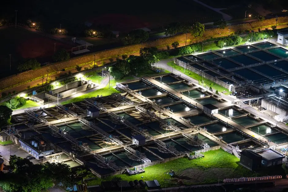
Three failure modes push the selection toward DAF when treating a milky, surfactant-stabilized CMP and fluoride blend. First, FOG and surfactant removal: post-CMP rinse carries slurry stabilizers and pad-residue oils that a lamella clarifier cannot capture, causing them to bleed into the overflow and foul the downstream UF. A DAF's 30–50 µm micro-bubbles scavenge these into the float layer where a paddle skimmer removes them. Second, colloidal and sub-10 µm particles: ceria and silica slurry particles do not settle in any reasonable residence time, and Stokes' law limits the efficacy of gravity-thickening in a basin. DAF attaches a bubble to each floc and floats the population, a mechanism documented in the IWA Publishing study on DAF of polishing wastewater (Shin et al., 2006, doi:10.2166/wst.2006.217). Third, RO protection: lower oil, grease, and colloidal loading on the downstream UF/RO means longer membrane life. If your design target is water reuse, the case for DAF is technical, and the broader context is laid out in the chip fab wastewater recycling 2026 blueprint.
Where a Lamella Clarifier Still Makes Sense
A lamella clarifier is the correct choice in three specific scenarios. When the fluoride stream has been pre-precipitated and thickened separately — CaF2 sludge at 2–5% solids, with no CMP carryover — the feed is dense, gritty, and settleable, allowing a lamella at 20–40 m/h surface loading to remove it cleanly with a fraction of the polymer dose a DAF would require. When jar testing confirms that FOG and colloidal loads are low and the operator prefers minimum mechanical complexity — no saturator, no air system, no skimmer, no PLC — a clarifier is operationally simpler. Finally, when CAPEX is the binding constraint on a brownfield project with an existing equalization basin that can be retrofitted with inclined plates, the HydropureWater lamella clarifier reduces chemical consumption by up to 30% versus conventional rectangular basins. Lamella is not the wrong tool, but it is the wrong default for an unsegregated CMP and fluoride blend.
2026 Selection Checklist for a Fab Utilities Engineer
Use this decision framework to evaluate your system requirements. If the stream contains CMP slurry, residual surfactant, or visible FOG, or if the reuse target is above 85%, choose DAF as the primary separator. If the stream is a segregated, thickened CaF2 sludge line with low FOG and unlimited footprint, choose a lamella clarifier. In most fabs, the optimal answer is hybrid: a HydropureWater dissolved air flotation system as the primary, sized 4–300 m³/h across 13 standard models, paired with a small lamella as a sludge thickener, both fed by a HydropureWater automatic chemical dosing skid for lime, PAC, and polymer. For sizing context and CAPEX/OPEX ranges, the semiconductor high-purity water system cost calculator provides the data required for procurement discussions.
Frequently Asked Questions
Can a DAF remove fluoride?
No. DAF is a physical solids-separation step. Fluoride is removed upstream by lime or CaCl2 precipitation, which converts dissolved fluoride into insoluble CaF2 particles. The DAF then floats or settles those CaF2 particles out of the stream; it does not remove the fluoride ion itself.
What TSS removal can a DAF achieve on CMP wastewater?
Field studies cited in the IWA Publishing paper on DAF of polishing wastewater report TSS removals typically in the 80–95% range with proper coagulant and flocculant dosing (per IWA Publishing 2006, doi:10.2166/wst.2006.217). A lamella clarifier on the same feed typically achieves 50–70%, which is the core reason DAF is the default primary separator for the blended CMP + fluoride stream.
Should CMP and fluoride wastewater be treated together or separately?
Treat them in a combined train after chemical precipitation, but with segregated upstream collection. The combined-treatment paper in the same IWA series (ResearchGate publication 239162496) is the reference for this hybrid configuration, which preserves the chemistry of each stream while allowing one DAF to handle the blended solids load.
How does DAF protect downstream RO for water reuse?
By removing FOG and colloidal particles that would otherwise foul UF/RO membranes, allowing fabs to hit the 70–90% reuse rates standard in the industry. Recent fouling-mode work, including the Sept 2026 Korean study on semiconductor UF/RO fouling, confirms that residual oil and grease is one of the dominant membrane foulants on fab reuse loops, which is exactly what DAF is best at stripping out.
What is the typical flow range for a fab-scale DAF?
The HydropureWater DAF covers 4–300 m³/h across 13 standard models, with skidded compact units typically rated up to ~66 GPM per skid and modular two-skid configurations for larger flows (per SigmaDAF Compact DAF spec, 2026-04-27). A complementary selection walkthrough is in the Marshall TX semiconductor wastewater DAF vs clarifier guide.