Why Paint Shop and Battery Wastewater Stress RO Membranes at EV Plants
Paint shop and lithium-ion cell wastewater at automotive and EV gigafactories carry colloidal solids that fall in the 0.1–10 µm range, the exact size window that reverse osmosis membranes cannot tolerate. Waterborne paint lines discharge waterborne acrylic and melamine resin emulsions, sub-10 µm pigment particles (TiO₂, carbon black, organic colorants), and surfactant-stabilized oil droplets that resist gravity settling. Battery anode-coating washwater adds graphite and silicon fines in the 1–5 µm range, PVDF and CMC binder residues, and trace lithium, nickel, and cobalt from formation cycling. A 2026 review of industrial wastewater treatment identifies paint and battery streams as significant heavy-metal and colloidal sources requiring multi-barrier treatment trains, not single-unit clarification (PMC review, 2026-02).
The relevant design metric is the Silt Density Index (SDI), not total suspended solids. SDI measures how quickly a 0.45 µm filter plugs under standard conditions, and it is the number RO membrane manufacturers use to warranty element life. Most RO manufacturers require feed SDI below 5 for limited operation and below 3 for guaranteed membrane life; some brackish-water elements specify SDI <2. Paint booth effluent without pretreatment routinely shows SDI of 15–25, and battery formation washwater sits in the 8–15 range. When SDI exceeds 5, RO flux drops 20–40% within hours, differential pressure climbs, and cleanings that would normally run quarterly become weekly. The decision for an EV process engineer is therefore not "DAF or UF" in the abstract, but "which unit gets the RO feed below SDI 3, consistently, on paint-shop and battery colloids."
A second consideration is the difference between floatable suspended solids and true colloids. Floatable TSS, free oil, and FOG respond to bubble attachment and rise under gravity; they are DAF's natural target. True colloids below 20 µm do not float reliably without coagulation chemistry because their surface charge keeps them dispersed. That distinction is what separates the two technologies in the sections that follow.
How DAF Works and What It Actually Removes
Dissolved air flotation (DAF) clarifies wastewater by attaching micro-bubbles to suspended matter so the aggregate floats. Pressurized water at 4–6 bar is saturated with air in a recycle side-stream, then released through a pressure-reduction valve at the inlet of a flotation tank. The pressure drop nucleates 10–100 µm bubbles that attach to particles and lift them to the surface, where a skimmer removes the float layer (Wikipedia DAF entry, accessed 2026; Racoman DAF explainer, 2026). Modern circular DAF units achieve this in about 3 minutes of residence; rectangular units need 20–30 minutes because they lack the spiral-scoop flow pattern (Wikipedia DAF entry).
The catch is that DAF only lifts what bubbles can attach to. True colloids below 20 µm are stabilized by surface charge and will not float reliably without coagulant (ferric chloride or aluminum sulfate) and polymer flocculant to grow them into a settle-and-floatable size. That chemistry step adds OPEX in the form of chemical consumption, sludge generation, and the operator time to tune dose against variable influent. DAF also benefits from lamella plate packing, which adds clarification surface area and improves solids capture (Wikipedia DAF entry).
Capacity range is a useful sizing sanity check. The Ecologix E-DAF series covers 130–3,700 GPM in 10 standard models with countercurrent scraping and optional enhanced floctube chemical contact (Ecologix, 2026). The DAF system covers 4–300 m³/h across 13 models with automatic skimming and micro-bubble contact, and is the typical pick for a paint-shop sidestream or a combined EV plant headworks.
For colloidal solids specifically, DAF effluent typically leaves 5–20 NTU turbidity and modest improvement in SDI, generally not enough to meet the SDI <3 RO threshold without a downstream membrane step. DAF is the correct bulk-removal step for FOG, free oil, and floated TSS, not the final guard for an RO unit.
How Ultrafiltration Works and Why It Targets Colloids Differently
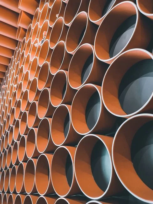
Ultrafiltration (UF) is a physical-size barrier, not a flotation process. Hollow-fiber UF membranes with 0.03 µm absolute pore size mechanically reject everything larger than that rating, including waterborne paint pigments, sub-micron TiO₂, anode carbon-black, PVDF/CMC binder residues, and most bacterial cells. There is no bubble, no flotation tank, and no chemistry required for the colloidal rejection step itself.
Operating practice at automotive and battery sites uses outside-in flow on PVDF hollow fibers. A hollow-fiber UF system in this duty accepts up to 300 ppm turbidity in the feed and produces permeate below 0.5 NTU, which correlates to SDI well under 3 on paint and battery influents (HydropureWater field data, 2026). The operating cycle is straightforward: 20–60 minutes of production followed by a 30–60 second backwash with air scour and permeate forward flush. That backwash recovers 90–95% of permeability, so chemical cleaning intervals of 1–3 months are normal on paint and battery feeds.
Because UF rejects colloids by size exclusion, it does not need coagulant or flocculant to function. That removes the chemical OPEX and the sludge-handling burden that a DAF-only train carries. UF does generate a backwash and CIP waste stream, typically 8–15% of feed flow, which is recycled to headworks. For an automotive or EV plant where chemistry handling and waste-to-treatment minimization are procurement constraints, that distinction is often the deciding factor.
Where UF falls short is on free oil and FOG above about 50 mg/L, which fouls the fiber surface and degrades permeability faster than backwash can recover. That is the engineering case for placing DAF upstream of UF on paint booth streams, and skipping DAF on most battery cell formation streams where FOG is low.
UF vs DAF: Spec-by-Spec Comparison for Colloidal Solids
The decision matrix below reflects what an automotive or EV process engineer actually weighs when defending an RO pretreatment choice to a plant manager: removal mechanism, target particle size, effluent quality, chemistry demand, footprint, and RO compatibility.
| Parameter | DAF | UF (0.03 µm PVDF) |
|---|---|---|
| Removal mechanism | Bubble attachment + skimming | Physical size exclusion (sieving) |
| Target particle size | 20–200 µm effective after flocculation | 0.03 µm absolute, all larger rejected |
| TSS removal | 80–95% (floatable fraction) | 99%+ on paint and battery colloids |
| Effluent turbidity | 5–20 NTU typical | <0.5 NTU typical |
| Effluent SDI | 5–10 typical, variable | <3, consistent (HydropureWater field data, 2026) |
| Chemistry required | Coagulant (ferric chloride or alum) + flocculant | None for colloidal step; periodic CIP |
| Residence / cycle time | 3 min (circular) to 20–30 min (rectangular) | Backwash every 20–60 min, 30–60 s burst |
| Footprint per m³/h | Larger, especially rectangular | Smaller, skid-mounted |
| RO compatibility as sole guard | No, SDI target not met reliably | Yes, meets SDI <3 threshold |
| OPEX driver | Coagulant + polymer dose, sludge haul | Membrane replacement (3–5 yr), CIP chemicals |
The verdict line for the procurement meeting: UF is the correct RO pretreatment guard for paint and battery colloids because it is the only one of the two that delivers SDI <3 consistently. DAF is the correct upstream bulk-removal step for FOG and floated TSS on paint booth streams, but it is not a substitute for a membrane barrier in front of an industrial RO system.
Matching the Choice to Paint Booth vs Battery Cell Streams
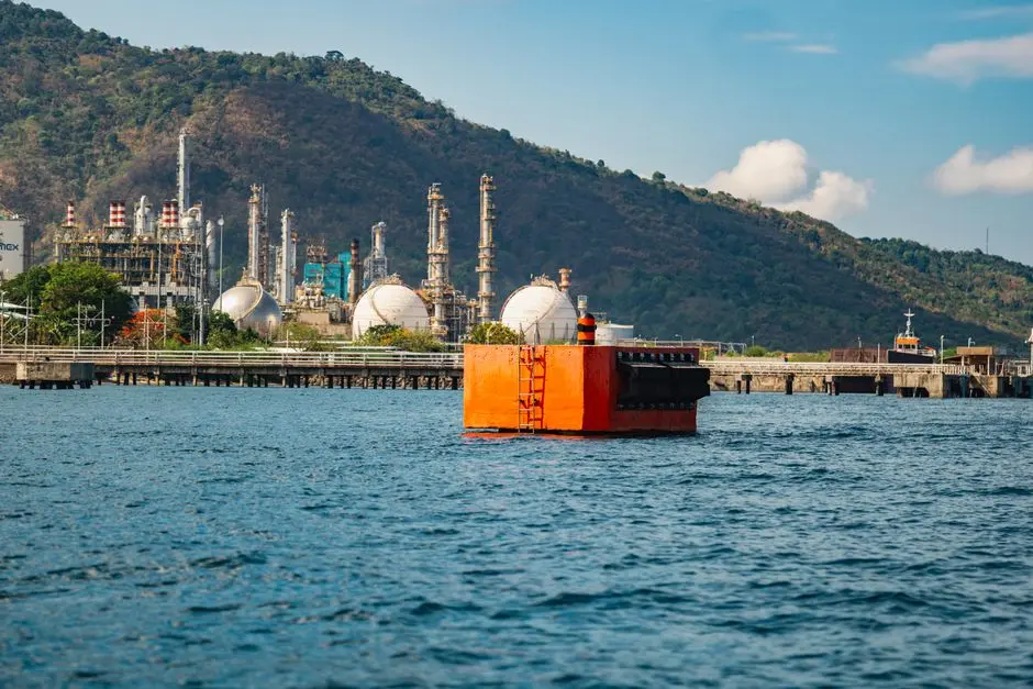
The two factory wastewater streams behave differently, and the pretreatment train should reflect that.
| Stream | Key contaminants | Recommended train | Why |
|---|---|---|---|
| Paint booth (waterborne) | High FOG, surfactant emulsions, sub-10 µm pigment colloids, TiO₂ | Coagulant dosing → DAF → equalization → UF → RO | DAF protects UF from FOG; UF protects RO from pigments and emulsified resin |
| Battery cell formation & coating washwater | Low oil, high colloidal carbon and binder fines, trace Li/Ni/Co | Equalization → 50 µm cartridge → UF → RO | FOG is low; DAF adds CAPEX without clear benefit; UF handles colloidal carbon and binder |
| Combined EV plant wastewater | Mixed FOG, paint pigment, anode fines | Screening → DAF → equalization → UF → RO | Single train handles both sidestreams; UF sized at 80–90% of DAF permeate flow to account for backwash recycle |
Capacity sanity check: a DAF system at 4–300 m³/h covers most automotive paint-shop flows, while a hollow-fiber UF system at 2,000–40,000 L/h covers the RO feed flow after DAF for a typical 50–200 m³/day RO skid. The UF is sized at roughly 80–90% of DAF permeate flow to absorb the backwash recycle stream returning to headworks.
For a battery-only plant, the train usually drops the DAF entirely. A formation washwater stream at pH 6–9 with <50 mg/L oil and SDI of 8–15 can go directly to a 50 µm cartridge guard followed by UF, and the RO feed will hold SDI <3. That is the cheapest defensible path for a cell-only facility.
Building the Right Pretreatment Train in 2026
The defensible pretreatment train for a paint-and-battery combined EV plant wastewater stream is: rotary bar screen (2–3 mm aperture) → pH adjustment and coagulant dosing → DAF → equalization tank (8–24 h HRT) → 50 µm cartridge filter → UF → RO → permeate UV. The order matters: screening first protects the DAF from rags and large debris; coagulant before DAF grows colloids into floatable floc; equalization smooths the 2–4× diurnal swings typical of paint-shop batches; the cartridge filter protects UF fibers from any floatable carryover; UF delivers the SDI <3 feed RO requires.
Add a multi-media filter only if DAF effluent TSS stays above 30 mg/L under steady-state operation, which usually happens when the coagulant dose is poorly tuned or the influent FOG spikes above design. A multi-media polish step before UF is cheaper than replacing UF membranes on a 6-month cycle, but it is not a default.
Order-of-magnitude OPEX intuition: a DAF train is dominated by coagulant and polymer consumption, typically 60–75% of its OPEX, with the rest in sludge hauling and power for the recycle pump. A UF train is dominated by membrane replacement on a 3–5 year cycle and intermittent CIP chemicals, with power for the feed and backwash pumps as a smaller line item. Spare-parts planning should include a stock of RO and UF membrane elements sized for one full change-out, plus two sets of CIP chemicals, before the plant goes live. More detail on adjacent pretreatment decisions for EV plants is covered in the DAF vs clarifier for EV and auto wastewater guide, and on related membrane-fouling research in the material-specific UF/RO fouling research brief.
Frequently Asked Questions
Can DAF alone protect an RO membrane from paint wastewater?
No. DAF effluent from a paint booth typically leaves SDI in the 5–10 range because sub-20 µm pigment and resin colloids pass through without aggressive coagulant chemistry, which is well above the SDI <3 RO manufacturers require for warranted element life.
Does UF need a DAF upstream?
Only if free oil or FOG exceeds roughly 50 mg/L. Paint booth streams with high FOG should run DAF first; battery formation and coating washwater with low oil can feed UF directly through a 50 µm cartridge guard.
What SDI does UF deliver to RO?
Typically below 3 on paint and battery influents, matching the RO manufacturer warranty threshold and giving the plant manager a defensible number to put in the equipment spec sheet.
How often does UF need chemical cleaning?
Every 1–3 months on paint and battery feeds, depending on solids load and backwash effectiveness. A well-tuned backwash cycle (30–60 second air-scour burst every 20–60 minutes) extends CIP intervals significantly.
Is DAF still needed if a plant only has battery wastewater?
Usually no, unless a formation step introduces hydrocarbon solvents that push FOG above the 50 mg/L UF tolerance. Most cell-only facilities can skip DAF and run equalization → cartridge → UF → RO.
Related Equipment
- industrial RO system — specifications, capacity range, and technical data