Why Westport Transportation Equipment Factories Are Re-evaluating Primary Separation in 2026
For a Westport, Connecticut transportation equipment factory in 2026, a Dissolved Air Flotation (DAF) system is the stronger default for streams high in free and emulsified oils, lubricants, and coolants (FOG typically >500 mg/L, TSS often 1,000–5,000 mg/L), where DAF delivers 90–95% FOG removal in a compact 5–50 m/h hydraulic loading footprint. A lamella (inclined-plate) clarifier becomes the better pick when the dominant load is heavy metal-bearing sludge from machining or stamping at lower FOG, and when lower CAPEX and chemical use (up to 30% less coagulant) outweigh DAF's faster kinetics.
Westport plants producing Tier-1 stampings, machined drivetrain components, E-coat/phosphate finished sub-assemblies, rail or aerospace fittings typically run four or five distinct wastewater streams that converge at a single pretreatment header. Stamping releases petroleum-based drawing oils and tramp grease; machining and EDM operations shed water-soluble and semi-synthetic coolants with tramp oil contamination; E-coat and phosphate rinse waters carry regulated metals (Zn, Ni, Cr) at low FOG; parts-washer effluent contains hot alkaline cleaner plus carry-out oil; final assembly wash bays contribute low-solids, intermittent oil spills. The combined load rarely looks the same hour to hour, which is why 2026 is a re-evaluation year.
CT DEEP enforces industrial discharge authorizations under the General Permit for Industrial Stormwater and individual Industrial Discharge Permits issued where site loadings warrant, while most Westport plants ultimately discharge to the Water Pollution Control Authority (WPCA) for sewer-side pretreatment limits. The 40 CFR 433 Metal Finishing categorical benchmarks — oil & grease 52 mg/L daily maximum, TSS 60 mg/L daily maximum, plus daily-maximum ceilings for Zn, Ni, Cr, Pb, Cd, Cu — set the practical envelope most Tier-1 suppliers design against even when their exact SIC code falls outside 40 CFR 433. Aging circular clarifiers installed 20–30 years ago, tighter metals tracking from customer ESG audits, PFAS scrutiny moving downstream from automotive supply chains, and the availability of high-rate lamella and hybrid flotation units have converged to make 2026 a natural specification year.
The DAF-vs-clarifier question is therefore not generic. The right answer is driven by which sub-stream dominates your combined flow.
Sub-Process Matrix: Which Stream Should Drive Your DAF-or-Clarifier Decision
Before talking to vendors, a Westport engineer should identify the design-case sub-stream. The table below maps the five typical operations to the dominant contaminant and the technology that fits it. FOG >500 mg/L or TSS >5,000 mg/L points to DAF as the primary; high-density inorganic sludge at low FOG points to a lamella clarifier; mixed oil + metals streams usually need a DAF primary followed by a lamella polish.
| Sub-process | Dominant contaminant | Typical FOG / TSS | Best-fit primary unit | Why |
|---|---|---|---|---|
| Stamping (press lube, drawing compound) | Free & emulsified oils, tramp grease | FOG 500–3,000 mg/L; TSS 500–2,000 mg/L | DAF (e.g., HydropureWater dissolved air flotation system) | Micro-bubble flotation captures free and emulsified oil that gravity settling cannot; float sludge at 3–8% DS dewaters cleanly downstream (S4). |
| Machining / coolant operations | Coolant emulsion, tramp oil, fine metal fines | FOG 200–1,500 mg/L; TSS 500–3,000 mg/L | DAF primary, lamella polish for metals | Emulsified coolant is the failure mode for clarifiers; pair the DAF with a HydropureWater high-efficiency lamella clarifier downstream to drop residual metals. |
| E-coat / phosphate / paint rinse | Pigment, regulated metals (Zn, Ni, Cr), low FOG | FOG <100 mg/L; TSS 100–800 mg/L | Lamella clarifier | High-density metal hydroxide sludge settles readily; lamella surface loading 20–40 m/h keeps plan area small (HydropureWater spec). |
| Parts washer (alkaline cleaner + oil) | Hot alkaline cleaner, emulsified oil | FOG 300–1,500 mg/L; TSS 200–1,000 mg/L | DAF with chemical pre-treatment | Emulsified oil after saponification needs bubble attachment; a DAF handles the heat and surfactant load better than a clarifier. |
| Assembly wash bay (final rinse) | Low solids, occasional oil spill | FOG <200 mg/L; TSS <200 mg/L | Lamella clarifier or simple plate pack | Intermittent, low-load stream; a small inclined-plate unit handles routine carryover without a saturator and compressor. |
Two operating parameters explain why DAF plants consume so much less floor space than conventional clarifiers at the same flow. DAF hydraulic loading rates run 5–50 m/h in classical units (S1), while a lamella clarifier operates at 20–40 m/h surface loading across its inclined plate pack (HydropureWater spec). Compared to a conventional circular clarifier — which needs very low overflow rates near 1–2 m/h to settle fine solids — a DAF is roughly 2–8× smaller in plan area at equal flow. The lamella narrows the gap, which is why space-constrained Westport retrofits increasingly choose lamella over circular gravity tanks.
How a DAF System Actually Treats Transportation Equipment Wastewater
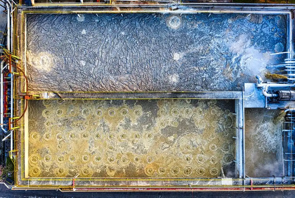
A DAF train is short enough to draw on a one-page PFD. Coagulant dosing (alum, ferric sulfate, or polyaluminium chloride) destabilizes colloidal oil and metal-hydroxide particulates; a flocculation stage with anionic polyacrylamide builds 0.5–3 mm flocs; the flocculated stream then meets a pressurized recycle in the flotation cell. A pump pulls 15–25% of clarified effluent, pressurizes it to 4–6 bar (60–90 psi) in a saturator vessel where compressed air dissolves into the water, and then releases the stream through needle valves or orifices back into the open tank. The pressure drop nucleates 10–100 µm micro-bubbles that attach to flocs and lift them to the surface, where a mechanical skimmer sweeps float sludge into a hopper.
Two numbers from the operating envelope matter for a capital request. DAF float sludge typically runs 3–8% dry solids (S4) — roughly 3–4× thicker than clarifier underflow — which directly reduces the size of any downstream belt press, screw press, or plate-and-frame press. The saturator pressure window of 4–6 bar (S4) sets the saturator vessel rating and the compressor sizing; operating at the lower end of that range trades bubble density for energy. Classical DAF units are documented to be inefficient above ~1% TSS (~10,000 mg/L) because the saturator orifices clog and recycle hydraulics are overwhelmed; the academic literature describes hybrid centrifugal-dissolved air flotation systems (e.g., the GEM system) that handle TSS >10,000 mg/L while occupying only 10–20% of the footprint of a classical DAF or clarifier (S1).
For a 2026 retrofit, the HydropureWater dissolved air flotation system ships in 13 models from 4–300 m³/h, with an integrated saturator and a matched automatic coagulant and flocculant dosing skid sized to the design flow.
How a Lamella (Inclined-Plate) Clarifier Treats the Same Stream
A lamella clarifier is a gravity settler with a stacked-plate pack inside. Coagulated and flocculated wastewater enters a flocculation zone, then flows upward through a series of parallel plates inclined at 55–60°. Solids settle onto the upper face of each plate, slide down the plate into a hopper at the bottom, and clarified water rises between the plates to a launder. The plate area provides an enormous effective settling footprint inside a small external volume.
Hydraulic surface loading is the design number: 20–40 m/h is the typical band on a HydropureWater lamella unit, which yields far smaller external dimensions than a conventional circular clarifier (1–2 m/h overflow rate at the same flow) — typically a 5–10× plan-area reduction (HydropureWater field data, 2026). HydropureWater's lamella spec also claims up to 30% lower coagulant consumption compared with conventional clarification, because the plate pack acts as a quiescent zone and improves floc utilization before sludge contacts the hopper.
What the lamella does not do well is also important for the comparison. Gravity settling cannot capture emulsified oil or low-density fine solids that lack the mass to overcome hydraulic upflow. Documented FOG removal for gravity clarifiers sits around 60–75% on oily industrial streams (S2), versus 90–95% for DAF on the same waste. A Westport plant that mistakenly selects a lamella for a coolant-dominated machining stream will find itself chasing oil breakthrough on the WPCA compliance meter.
DAF vs Clarifier: 2026 Side-by-Side for a Westport Transportation Plant
This is the table to paste into the capital memo. Footprint, FOG removal, and best-fit sub-process are the three columns procurement will look at first; CAPEX band, OPEX, and sludge dryness come next. Numbers marked as vendor-reported are honest about their origin — they bracket expectation, they do not guarantee a CT-specific result.
| Parameter | DAF | Conventional Clarifier | Lamella Clarifier |
|---|---|---|---|
| FOG removal | 90–95% (S2; S4) | ~60–70% (S2) | ~65–75% (vendor-reported) |
| TSS removal (post-coag/floc) | 85–95% | 70–90% | 80–95% |
| Hydraulic loading / surface loading | 5–50 m/h HLR (S1) | 1–2 m/h overflow | 20–40 m/h (HydropureWater spec) |
| Plan area at 50 m³/h (qualitative) | 1–2 m² flotation zone | ~25–50 m² (large circular tank) | ~1.5–2.5 m² plate area footprint |
| Float / sludge solids | 3–8% DS float (S4) | 1–2% underflow | 1–2% underflow |
| CAPEX order of magnitude (50 m³/h, 2026 USD) | Higher (vessel, saturator, compressor, skimmer) | Lowest (concrete or steel tank) | Moderate (tank + plate pack) |
| OPEX drivers | Compressor, polymer, recycle pumping | Pumping, occasional polymer | Pumping, polymer (up to 30% lower than conventional) |
| Sensitivity to flow surges | Moderate (saturator hydraulics) | High (solids washout) | Moderate |
| Best-fit sub-process | Stamping, machining coolant, parts washer | Heavy inorganic sludge, low FOG | E-coat/phosphate rinse, assembly wash, polishing step |
Two cited anchors that should appear in the supporting memo: a food-processing case where a DAF achieved 95% FOG removal versus a clarifier's 70% on the same stream (S2, vendor-reported), and a mining case where a clarifier reduced solids 90% at lower cost (S2). Neither is a Westport stamping line, but together they bracket the practical spread.
For the FOG-dominated streams that dominate Westport Tier-1 parts plants, the operational driver usually decides. The DAF family of DAFs in the HydropureWater dissolved air flotation system covers 4–300 m³/h in 13 models, so a 50 m³/h shop selects the same product family a 200 m³/h Tier-1 plant uses. The downstream plate-and-frame sludge dewatering press sees a 3–8% DS float cake rather than a 1–2% underflow, which cuts dewatering cycle time and polymer use.
Worked Example: 50 m³/h Stamping + Machining Shop in Westport
Consider a fictional but plausible Tier-1 supplier in Westport combining a stamping cell (two 800-ton presses, drawing compound at 6% concentration) with a machining cell (six CNC mills, three EDMs, semi-synthetic coolant). The combined wastewater header runs at 50 m³/h with intermittent 2× batch spikes, pH 7–9, temperature 20–30 °C, FOG ~800 mg/L, TSS ~2,000 mg/L. The compliance envelope targets oil & grease near the 40 CFR 433 daily maximum of 52 mg/L and TSS near 60 mg/L, with monthly metals tracking for Zn and Ni.
DAF option. Sizing at a conservative HLR of 20 m/h gives a flotation zone of about 2.5 m² (typical cell footprint roughly 1.6 m × 1.6 m), saturator at 5 bar, 10 m³/h recycle (~20% of throughput), and anionic polyacrylamide dose of 3–5 mg/L with ferric chloride at 50–80 mg/L for emulsion break. Expected float solids 3–8% (S4); skimmings go straight to a small plate-and-frame sludge dewatering press sized to roughly 1–2 m³/h cake throughput. Compressor draw is on the order of 0.5–1.0 kW per m³/h, and the polymer skid is sized to peak dosing. CAPEX is dominated by the stainless vessel, saturator, compressor, and skimmer; OPEX is dominated by compressor energy, polymer, and the recycle pump.
Lamella option. At a surface loading of 25 m/h the lamella needs roughly 2 m² of projected plate area — plan-area competitive with the DAF, but with a shorter tank and a more complex plate pack. The clarifier cannot, however, hit the 52 mg/L FOG ceiling on this stream with FOG around 800 mg/L; it would need a preceding DAF or an emulsion-breaking pretreatment to get there. Underflow at 1–2% DS requires a larger downstream dewatering press.
The defensible decision for this profile is DAF primary, with a small lamella or polishing filter downstream only if a segregated E-coat sub-stream needs a dedicated metal-removal step. Putting the entire 50 m³/h through a lamella first will fail the FOG compliance point.
2026 Selection Decision Tree for Westport Plants
Four steps, applied in order, get to a defensible specification.
Step 1 — Characterize. Pull representative samples across a full shift. You need TSS, FOG, total metals, pH, temperature, and a flow histogram. Batch discharge patterns (stamping coolant dumps, wash-bay spills) are as important as the average loading.
Step 2 — Route by contaminant. If FOG is consistently >500 mg/L or emulsified oils are present, specify a DAF as the primary. If FOG is <200 mg/L and TSS is dominated by dense metal-bearing sludge, specify a lamella clarifier. If both — for example, a coolant stream combined with phosphate rinse — specify a DAF primary followed by a lamella polish for residual metals.
Step 3 — Check physical constraints. Indoor retrofit with a low ceiling favors a short-tank lamella or a low-profile DAF. Outdoor with room for a 2.5 m tall tank gives the conventional DAF layout room to run. If TSS regularly exceeds 5,000 mg/L, evaluate a hybrid centrifugal-DAF whose footprint is only 10–20% of a classical DAF (S1).
Step 4 — Confirm with jar tests + pilot, then specify the chemical system. Jar tests should bracket coagulant type, dose, and flocculation time; pilot data validates HLR, surface loading, and float or sludge solids. The chemical system is not optional — a matched automatic coagulant and flocculant dosing skid drives the performance of whichever primary you select, and the selection logic for that skid is detailed in this industrial coagulant and flocculant dosing engineering guide. For comparison context outside the Westport market, the DAF vs clarifier for EV and auto parts factories in Bradenton guide and the DAF or clarifier for transportation equipment wastewater in Milton guide reach similar conclusions from different regulatory baselines.
Frequently Asked Questions
What influent FOG and TSS numbers point to a DAF instead of a lamella clarifier for a Westport transportation plant?
DAF is the correct primary once FOG is consistently above 500 mg/L or TSS exceeds 5,000 mg/L (S1, S4). Below 200 mg/L FOG with mostly dense metal hydroxide sludge, a lamella clarifier typically does the job in less floor space and with up to 30% lower coagulant consumption.
Is a DAF or a clarifier more cost-effective for a small Tier-1 parts shop under 50 m³/h in Connecticut?
For FOG-dominated streams the DAF's higher CAPEX is recovered through lower discharge surcharges, fewer WPCA compliance excursions, and 3–8% DS float sludge that dewateres faster on a plate-and-frame press (S4). For low-FOG, high-metal streams a lamella is more cost-effective because it avoids the compressor and saturator OPEX.
Do Westport plants discharging to the WPCA face stricter limits than 40 CFR 433 metal finishing benchmarks?
Yes — CT DEEP-issued industrial discharge permits and the local WPCA sewer use ordinance typically set site-specific oil & grease, TSS, and metals limits that may be tighter than the 40 CFR 433 daily-maximum ceilings of 52 mg/L oil & grease and 60 mg/L TSS. The practical approach is to design against the stricter of the two envelopes and to reconfirm with the WPCA during the 2026 permit cycle.
Can a DAF and a lamella clarifier be used together at a Westport plant?
Yes. The most common 2026 arrangement is a DAF primary for FOG and emulsified oil removal, followed by a lamella clarifier as a polishing step for residual metals from a segregated E-coat or phosphate rinse stream. The hybrid reduces polymer demand and tightens the metals compliance margin (S1, S2).