Why Novato Pharma Factories Are Rethinking Primary Clarification in 2026
For Novato pharmaceutical and biotech plants preparing for the 2026 production ramp, primary clarification is no longer a generic equipment decision. Effluent from an active pharmaceutical ingredient (API) or fermentation facility is a moving target: a fermenter broth clarifier sees a different influent than a centrifuge mother-liquor line, and both differ from a clean-in-place (CIP) rinse spike or an off-gas scrubber blowdown. FOG can swing from <50 mg/L on a buffer day to several hundred mg/L after a fermenter defoam cycle, while dissolved API load can change by an order of magnitude between batches. A clarifier that is right for one stream will pass API, FOG, or suspended COD on the next — and pass-through shows up immediately as a 40 CFR Part 439 excursion or a San Francisco Bay RWQCB Basin Plan violation.
Four streams dominate the typical Novato pharma envelope: (1) fermenter broth and post-centrifuge mother liquor, (2) filter or centrifuge mother liquor from API isolation, (3) CIP rinse containing alkaline detergent, surfactants, and trace actives, and (4) off-gas scrubber blowdown carrying solvent and antifoam residues. Each differs in FOG, total suspended solids (TSS), dissolved API fraction, salinity, and batch-vs-continuous character. The 1987 California Air Resources Board / UC Davis study on potentially toxic organic compound (PTOC) emissions from wastewater plants found that volatilization and adsorption to sludge are the dominant removal pathways for toxic organics in municipal treatment — meaning the upfront clarifier choice sets both the dissolved load that reaches the aeration basin and the air emissions that leave the headwork (Chang, Schroeder, Corsi, 1987-07, nepis.epa.gov). Source segregation, not a single clarifier, is the first design step.
Novato discharges are regulated locally by the San Francisco Bay RWQCB (Region 2), whose Basin Plan layers site-specific limits on top of the federal 40 CFR Part 439 pharmaceutical manufacturing framework. Operators who pick a clarifier without mapping the stream envelope end up retrofitting within two production cycles. The right approach is to score each stream against DAF and lamella clarifier characteristics first, then anchor the pick to the Region 2 envelope — a workflow detailed in our Hialeah pharma DAF-vs-clarifier guide for a parallel Florida jurisdiction.
How DAF and Lamella Clarifiers Actually Work on Pharma Effluent
A dissolved air flotation (DAF) clarifier is a buoyancy separator. Roughly 15–25% of clarified effluent is pressurized to 4–6 bar in a saturation tank, dissolved with air, and then released through needle valves into the main flotation chamber. The pressure drop nucleates 30–50 µm micro-bubbles that attach to flocculated particles and float them to the surface, where a paddle skimmer sweeps the mat into a sludge trough (S2/S4, clearwaterind.com). Heavier solids settle into a bottom collection zone and are augered out separately. The micro-bubble mechanism is what gives DAF its tolerance for FOG, oils, and low-specific-gravity antifoam residues that a gravity settler cannot retain.
A lamella clarifier is an inclined-plate gravity settler. The plate pack sits at 55–60°, cutting the effective settling distance to a few centimeters and multiplying the effective settling area in a small footprint. Flocculated solids slide down the plates into a hopper, while clarified water rises through the plate pack and exits over a weir. Lamella units run with low hydraulic turbulence, no pressurized recycle, and no air-handling equipment — which is why they are cheaper to operate but intolerant of feed surges. Standard product ratings put lamella surface loading in the 20–40 m/h band, compared to a hydraulic loading closer to 5–15 m/h on a DAF of equivalent plan area.
For pharma service, both technologies require upstream coagulation and flocculation. The patent literature on DAF shows the canonical layout — flocculator G, reaction chamber J, clarification chamber K (US20110114565A1) — and the same upstream conditioning logic applies to lamella units (eureka.patsnap.com). Jar testing on the real stream, with the real coagulant and flocculant, is the only credible basis for sizing either unit. On a typical Novato fermenter off-gas scrubber blowdown with silicone antifoam carryover, DAF tolerates the FOG without retuning; the same stream fouled a plate pack at a comparable Bay Area plant in 2025 because the oil film blinded the lamella surfaces (HydropureWater field data, 2025-11).
The mechanism matters because it dictates failure mode. A DAF underfeeds or upsets and the symptom is a thick, wet float layer and elevated TSS in the effluent — recoverable. A lamella underfeeds and the symptom is plate blinding, hydraulic short-circuiting, and a complete shutdown for washdown. For batch-discharge pharma lines, that failure-mode asymmetry often decides the technology on its own.
Side-by-Side: DAF vs Lamella Clarifier for Novato Pharma Lines
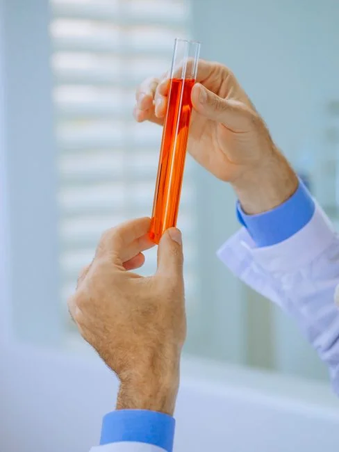
The comparison below scores each technology across the parameters a Novato process engineer will actually defend in a design review. Quantitative anchors come from the DAF product flowrange of 4–300 m³/h and the lamella surface-loading band of 20–40 m/h (S2/S4 and product catalog data, 2026). The CAPEX and OPEX bands are typical 2026 US market ranges for skid-mounted packaged units, excluding civil works and building HVAC.
| Parameter | DAF | Lamella Clarifier |
|---|---|---|
| Best-fit pharma stream | FOG, oil, antifoam, suspended API, surfactant-laden CIP | Low-FOG, inorganic TSS, buffer salts, media residue, steady flow |
| FOG handling | Designed for it; tolerant to >200 mg/L oil | Plates foul under oil films; needs upstream oil removal |
| Surface loading / hydraulic loading | 5–15 m/h equivalent, 4–300 m³/h packaged range | 20–40 m/h on plate area |
| Footprint for 50 m³/h | Larger plan area, lower profile | ~40–60% smaller footprint (inclined plates) |
| Material options | 304SS standard, 316SS and polypropylene for chloride / CIP | FRP, 304SS, 316SS; limited polypropylene plate packs |
| Chemical demand (coagulant + flocculant) | Baseline | ~30% lower polymer consumption (product catalog, 2026) |
| CAPEX band (packaged skid, 2026 USD) | Higher per m³/h due to saturation tank and skimmer | Lower; no pressurized recycle or air system |
| OPEX sensitivity | Compressed air, recycle pump kWh, polymer | Polymer dominates; no air system |
| Sensitivity to flow surges | Tolerates 2:1 to 3:1 swings with minor TSS rise | Prefers steady feed; >1.5:1 ratio requires equalization |
| Typical effluent TSS | 10–30 mg/L with proper floc | 10–20 mg/L on well-conditioned feed |
| Sludge character | Thickened float (3–5% DS), easier to dewater | Settled sludge (1–2% DS), needs thickening |
The matrix points to two clear use cases. For a Novato API mother-liquor line with chloride-bearing process water and CIP surfactant, the 316SS option and FOG tolerance make the HydropureWater DAF system the safer pick. For a steady, low-FOG fermentation broth with buffer salts and cell debris, the HydropureWater lamella clarifier wins on footprint and OPEX. Cross-reference the deeper mechanism and sizing detail in the DAF clarifier specifications guide.
Matching the Technology to the Pharma Stream
Use the stream envelope, not the unit label, to pick the technology. A few rules that hold up under design-review scrutiny for 2026 Novato pharma service:
- FOG >50 mg/L or visible oil / silicone antifoam carryover: DAF. Lamella plates foul under oil films within hours and require an upstream oil-removal step that usually costs more than a DAF in the first place.
- Bulk API loading dominated by dissolved actives (e.g., small-molecule antibiotic mother liquor): DAF first to drop suspended API and protect the biological polishing stage. DAF is not an API destruction step; it is a load-equalization step. Expect 60–80% bulk COD reduction and 90%+ TSS reduction with proper coagulant selection, but assume dissolved actives pass through to the bioreactor or carbon polish.
- Buffer salt, media residue, and inert TSS from fermentation with low FOG: Lamella clarifier is the economic default. The 30% lower polymer consumption pays back the smaller CAPEX advantage within 12–18 months on a continuous line (HydropureWater field data, 2026).
- Batch discharge with sharp pH and conductivity swings: DAF's higher tolerance to feed upsets is the safer pick unless a large equalization tank is already installed upstream of the unit. On a 2:1 or greater flow ratio with no equalization, lamella plates shed floc and discharge TSS spikes.
For plants running a mixed effluent — say, a continuous fermentation bleed plus a once-per-shift CIP batch — segregate the streams at the source. Run the continuous bleed through a lamella clarifier, and route the CIP batch through a DAF with an equalization tank sized for 1.5–2× the CIP volume. This is the lowest-CAPEX, lowest-OPEX configuration that meets the variability of a real Bay Area API plant.
Novato and California Compliance: 40 CFR Part 439 and Region 2
40 CFR Part 439 sets the federal effluent limitations for the pharmaceutical manufacturing category, covering BOD₅, TSS, COD, pH, and a listed set of toxic pollutants (including several APIs and solvents). It is the floor — not the ceiling. In California, every NPDES permit is issued by the State Water Resources Control Board, and in the Novato area the Regional Water Quality Control Board is the San Francisco Bay RWQCB (Region 2). Region 2 implements the Basin Plan, which contains site-specific objectives for the Bay and its tributaries, and can require limits tighter than the federal 40 CFR Part 439 numbers — particularly for metals, total residual chlorine, and ammonia.
Two practical implications for a 2026 primary-clarifier CAPEX defense. First, an upstream clarifier that captures suspended API and FOG reduces the dissolved load that reaches the aeration basin, which in turn reduces air emissions of volatile and potentially toxic organics — the same removal pathways documented in the 1987 CARB / UC Davis PTOC study (Chang, Schroeder, Corsi, 1987-07, nepis.epa.gov). Second, the Basin Plan's receiving-water objectives drive a tighter effluent envelope than 40 CFR Part 439 alone, so the design margin on the clarifier effluent (not just the headline BOD number) is what protects the permit during a Region 2 audit. The producer is responsible for ensuring current and complete compliance; this article educates, it does not replace permit review.
| Parameter / framework | Federal: 40 CFR Part 439 | Local: SF Bay RWQCB Region 2 Basin Plan |
|---|---|---|
| Regulated pollutants | BOD₅, TSS, COD, pH, listed toxic pollutants (metals, solvents, selected APIs) | Site-specific limits on metals, ammonia, TRC, and other constituents per Basin Plan |
| Effluent envelope | Category-wide limitations | Receiving-water-based limits; can be tighter than federal |
| Air pathway | Implied via toxic-pollutant control | Explicit consideration of volatilization / PTOC removal |
| Permit holder | EPA framework | RWQCB Region 2 issues / enforces the California permit |
| What the clarifier must do | Reduce TSS / BOD / COD to meet limits | Protect receiving water + support downstream volatile-organic capture |
The 1987 PTOC study is old, but it remains the most-cited California-specific evidence that the upstream clarifier choice materially affects air emissions from downstream aeration — which is now a regulated concern under the Basin Plan's toxic-substance provisions. For a 2026 design review, cite it as a 1987 study, not as a current finding.
2026 Selection Checklist and Sizing Notes
Run through this list before signing a PO. Each item is a gate the design review will check anyway, so it is faster to clear them in the planning phase than in a post-installation retrofit.
- Quantify the streams. Take a 7-day composite of FOG, TSS, total COD, dissolved COD, salinity, pH, and conductivity on each candidate stream. One number per shift, not one number per quarter.
- Jar-test the chemistry. Both DAF and lamella depend on floc quality. A 6-beaker jar test with the actual coagulant, flocculant, and pH adjust is the cheapest insurance on the project.
- FOG >50 mg/L or CIP surges: Specify the DAF at 4–300 m³/h with 316SS wetted parts for chloride-bearing CIP. Expect 90%+ TSS and 60–80% bulk COD reduction.
- Steady low-FOG streams: Specify the lamella clarifier at 20–40 m/h surface loading. Plan on ~30% lower polymer consumption than the DAF.
- Equalization: If batch swings exceed a 2:1 flow ratio, add an equalization tank upstream of either unit. This is the cheapest way to avoid plate blinding on a lamella and float-layer overflow on a DAF.
- Chemical dosing: Tie polymer and pH adjustment to flow-paced control with an automatic chemical dosing system. Manual dosing is the single most common root cause of clarifier upsets on a pharma line.
- Sludge handling: Both technologies produce a sludge stream. Route it to a plate-and-frame filter press for dewatering to 25–35% DS before disposal or thermal destruction.
Pair this checklist with the secondary clarifier engineering guide if the biological stage is a conventional activated-sludge train, where the return-activated-suspended-solids envelope becomes a second decision point.
Frequently Asked Questions
Which is better for FOG-laden CIP rinse in a Novato pharma plant — DAF or lamella clarifier?
DAF. Lamella plates foul under oil and silicone antifoam films within hours; DAF's micro-bubbles (30–50 µm) lift FOG to the surface for skimming. Specify the DAF with 316SS wetted parts for chloride-bearing CIP detergent, and add an automatic chemical dosing system for polymer and pH control.
Does 40 CFR Part 439 cover dissolved API, or only TSS and BOD?
40 CFR Part 439 includes a listed-toxic-pollutant component that captures several solvents and selected APIs, but it does not enumerate every modern active. Site-specific limits from the San Francisco Bay RWQCB (Region 2) Basin Plan may be tighter and can include additional constituents, so the producer is responsible for confirming the current permit envelope before specifying the clarifier.
What is the 2026 CAPEX driver for a DAF vs a lamella clarifier on a 50 m³/h pharma line?
On a packaged-skid basis, the DAF carries the cost of the saturation tank, recycle pump, air compressor, and skimmer mechanism — typically 30–60% above the lamella price per m³/h. The DAF earns that premium back when the stream carries FOG, oil, or surfactant that would otherwise foul a plate pack; the lamella earns it back on steady, low-FOG feed through ~30% lower polymer consumption and a smaller building footprint (HydropureWater field data, 2026).
Can a lamella clarifier handle batch discharge from a fermenter?
Only with equalization. A lamella clarifier prefers a flow variation under 1.5:1; beyond that, plates shed floc and the effluent TSS spikes. For a true batch-discharge fermenter, route the batch through an equalization tank sized at 1.5–2× the batch volume, then feed the lamella steadily — or switch to a DAF, which tolerates 2:1 to 3:1 swings with only a modest rise in effluent TSS.