What Is a Secondary Clarifier in Activated Sludge Treatment?
A secondary clarifier is a gravity sedimentation tank that separates biological floc from mixed liquor after aeration. Typical MLSS feed ranges from 2,000 to 4,000 mg/L. Clear effluent rises to weirs at 0.5–1.0 m depth, targeting below 30 mg/L TSS for discharge and below 10 mg/L for reuse under ISO 16075:2020.
After the aeration basin, mixed liquor enters the tank and velocity drops so heavier solids settle. Distinct layers form: clear effluent at the top, a thickening zone in the middle, and a sludge blanket at the bottom. Return activated sludge (RAS) usually runs at 25% to 100% of influent flow.
Higher RAS ratios can stabilize settling, yet they raise pumping energy. Operators typically aim for a blanket of 0.8–1.2% solids for return or further dewatering.
| Zone | Description | Typical Depth | Key Performance Indicator |
|---|---|---|---|
| Effluent Zone | Treated water rising to weirs | 0.5 - 1.0 m | Effluent TSS (<30 mg/L) |
| Clarification Zone | Initial settling of floc | 1.0 - 2.0 m | Flocculation & Settling |
| Thickening Zone | Sludge consolidation | 1.5 - 3.0 m | Sludge Blanket Density |
| Sludge Blanket | Concentrated settled solids | Variable (0.5 - 2.0 m) | Sludge Return Rate (RAS) |
How do you select a clarifier system for industrial wastewater?
Start with influent data before choosing geometry. Record average and peak flow, TSS, temperature, and whether the process is batch or continuous. Those values set surface loading, solids loading, and sludge-removal needs. Plants that need tighter numeric limits should review published engineering specifications and loading standards alongside site measurements.
Match equipment type to those constraints. Highly variable flow often favors circular tanks with robust scrapers. Steady high flow with available land also suits circular designs. Very high TSS loads, such as food-processing streams, often fit lamella plate packs.
When footprint is limited, a High-Efficiency Sedimentation Tank (Lamella Clarifier) can cut area demand by up to 50% versus conventional tanks.
Size the surface with Area (m²) = Peak flow (m³/day) / Surface loading rate (m³/m²/day). A 2,000 m³/day food plant at a conservative 15 m³/m²/day needs about 133 m². Using the peak of 4,000 m³/day at the same rate raises the area to 267 m².
CAPEX often falls near $500–$1,200/m² for circular units and $400–$900/m² for rectangular units. OPEX for energy and maintenance commonly sits between $0.02–$0.05/m³ treated.
| Step | Action | Key Considerations | Example Data |
|---|---|---|---|
| 1 | Characterize Influent | Flow rate (peak/avg), TSS, Temp, Variability | Food processing: 2,000 m³/day avg, 4,000 m³/day peak, 5,000 mg/L TSS |
| 2 | Match Clarifier Type | Space, flow variability, TSS load | High TSS → Lamella; Variable Flow → Circular |
| 3 | Size Clarifier | Peak flow, appropriate SLR | Area = 4,000 m³/day / 15 m³/m²/day = 267 m² |
| 4 | Evaluate Sludge Removal | CAPEX vs. OPEX, maintenance needs | Scrapers: Lower CAPEX, higher maintenance; Suction: Higher CAPEX, lower maintenance |
| 5 | Budget & ROI | CAPEX, OPEX, potential savings | CAPEX: $400-$1200/m²; OPEX: $0.02-$0.05/m³; 10% TSS improvement = $20k/yr savings |
Which design criteria separate primary, secondary, and lamella options?
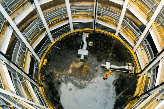
Primary tanks remove gross settleable solids before biology, typically cutting 50–65% TSS and yielding thicker sludge at 3–6% solids. Units after aeration separate activated-sludge floc and usually reach 92–97% TSS removal, with thinner return solids at 0.8–1.2%. Lamella packs add inclined plates to raise effective settling area and can run surface rates up to 60 m³/m²/day. Where floatable oils dominate instead of settleable floc, compare results with a dissolved air flotation (DAF) process train before freezing the flowsheet.
Circular tanks distribute flow evenly and avoid corner sludge pockets. They handle large flows well, yet capital cost and footprint are higher. Rectangular tanks suit tight sites and modular expansion. Chain-and-flight or traveling-bridge collectors move sludge, sometimes with less uniform distribution and higher conveyance energy.
Lamella units excel in retrofits, though plate cleaning and influent swings need more attention. Field data show circular designs often near 95% TSS removal. Rectangular units commonly land near 92%. Lamella systems can exceed 96% with sound inlet control.
Scraper blades sweep circular floors to a center hopper. Rectangular trains use flights or suction headers. Lamella packs rely on hopper slope beneath the plates.
| Clarifier Type | Sludge Removal | Primary Advantages | Primary Limitations | Typical SLR (m³/m²/day) | Typical TSS Removal Efficiency |
|---|---|---|---|---|---|
| Circular (Center/Peripheral Feed) | Scraper Blades | Uniform flow, low maintenance, large capacity | Higher CAPEX, larger footprint | 20-40 (Municipal) 10-20 (Industrial) |
95% |
| Rectangular (Chain-Flight/Traveling Bridge) | Flights/Suction Headers | Space-efficient, modular, lower CAPEX | Uneven sludge distribution, higher energy use | 20-35 (Municipal) 10-15 (Industrial) |
92% |
| Lamella (Inclined Plates) | Hopper Slope | Compact footprint, high-rate settling, ideal for retrofits | Higher maintenance, sensitive to variability | Up to 60 | 96%+ (with optimal design) |
Hydraulic Loading, Sludge Concentration, and Effluent Targets
Surface loading rate guides area. Municipal plants often use 20–40 m³/m²/day. Industrial trains usually hold 10–20 m³/m²/day because loads swing harder. A 5,000 m³/day facility at 40 m³/m²/day needs at least 125 m² of surface.
Solids loading for activated sludge typically stays between 3–6 kg/m²/h. Crossing the EPA 2024 mark of 5 kg/m²/h raises washout risk. RAS should thicken to 0.8–1.2% solids. Waste activated sludge (WAS) often reaches 1.5–3.0% solids before dewatering.
Discharge permits commonly allow below 30 mg/L TSS. Reuse loops may need below 10 mg/L. Semiconductor RO pretreatment can demand below 5 mg/L TSS. Hydraulic retention time is often 2–4 hours in municipal service and 1–2 hours in denser industrial MLSS.
| Parameter | Typical Range / Target | Unit | Significance |
|---|---|---|---|
| Surface Loading Rate (SLR) | 20-40 (Municipal) 10-20 (Industrial) |
m³/m²/day | Determines required clarifier area for a given flow rate |
| Solids Loading Rate (SLR) | 3-6 | kg/m²/h | Prevents sludge blanket washout; critical for settling |
| Sludge Concentration (RAS) | 0.8-1.2 | % solids | Efficiency of sludge return to aeration |
| Sludge Concentration (WAS) | 1.5-3.0 | % solids | Pre-dewatering concentration |
| Effluent TSS | <30 (Discharge) <10 (Reuse) <5 (High Purity Industrial) |
mg/L | Compliance and process requirements |
| Hydraulic Retention Time (HRT) | 2-4 (Municipal) 1-2 (Industrial) |
Hours | Time for settling to occur |
Field Case: Variable Flow at a Semiconductor Fab

In Suzhou, a semiconductor fab saw effluent TSS jump from 25 mg/L to 80 mg/L after a rectangular chain-and-flight unit was installed. Variable plant flows disrupted blanket control. Downstream RO membranes began fouling earlier than planned. Chemical dosing costs rose about 30% while permit risk climbed.
The mismatch was hydraulic, not biological. Space-saving geometry could not hold stable blankets when peaks arrived. For similar fabs, circular scrapers or carefully baffled inlets usually tolerate swings better. A 10% gain in TSS removal on a 5,000 m³/day plant can cut downstream chemical spend by about $20,000 per year.
Settling Failures and Practical Fixes
High effluent TSS above 30 mg/L often traces to blanket washout, short-circuiting, or excess RAS. Useful responses include lowering peak hydraulic load, holding RAS near 50–75% of influent, and dosing polymer at 0.5–2 mg/L to strengthen floc. For a deeper field checklist covering common operational problems in secondary clarifiers, use the linked troubleshooting notes before changing hardware.
Rising sludge usually points to denitrification gas or septic H₂S. Raising RAS can add oxygen and shorten sludge age. Confirmed denitrification may need nitrate control in anoxic zones. Uneven blankets improve with inlet distributors or baffles, especially outdoors where wind shears the surface.
RAS below 0.8% solids often means excess WAS or weak thickening. Cut WAS, deepen the tank, or add a dedicated thickener. Inspect weirs and scum baffles weekly. Calibrate blanket sensors monthly.
How often should industrial plants clean and verify performance?

Weekly weir and scum-baffle checks catch most hydraulic faults early. A full drain-down and internal clean every 1–2 years is typical. Clean sooner if sludge buildup reaches about 30% of tank depth. Industrial wastewater can still use these settlers when surface loading stays near 10–20 m³/m²/day.
Challenging food or pharma loads may need polymer at 1–3 mg/L. For a quick size check, divide peak flow by the chosen surface loading rate. A 3,000 m³/day plant at 30 m³/m²/day needs 100 m² minimum.
Well-run units commonly deliver 92–97% TSS removal under EPA 2024 benchmarks. Some industrial trains with lamella hardware and tertiary filters report 99% or higher. Waste solids then move to screw press or other sludge dewatering options sized for 1.5–3.0% feed.
Who this is for / Who should look elsewhere / Next step
This guide is for plant engineers, operations managers, and procurement teams sizing settlers after activated sludge. It suits fabs, food plants, and other industrial sites that must hold TSS near discharge or reuse limits. Teams treating mainly emulsified oil with little settleable floc should evaluate DAF first. Municipal-only projects with steady low solids may use simpler standard loadings without industrial derating.
Next, gather peak flow, MLSS, and effluent TSS targets, then compare circular, rectangular, and lamella options against the tables above. If you want a vendor sizing pass on flow and solids data, send those figures for a quote review.
Related Equipment
- HydropureWater’s lamella clarifiers for high-rate settling — view specifications, capacity range, and technical data
- sludge dewatering systems for secondary clarifier waste — view specifications, capacity range, and technical data
Need a customized solution? Request a free quote with your specific flow rate and pollutant parameters.
Further Reading
- Learn how dissolved air flotation (DAF) systems compare to secondary clarifiers
- Discover sludge dewatering options for secondary clarifier waste