What 2026 Pretreatment Compliance Actually Requires Near Pulaski
The 2026 binding constraint for any EV or auto plant discharging to a sewer in the Pulaski–Smyrna industrial corridor is almost never the federal categorical standard; it is the local POTW limit developed under 40 CFR 403.5(c). The statutory hook is Clean Water Act §307(b), which directs EPA to set pretreatment standards for pollutants that pass through or interfere with POTW operations, and §402(n), which authorizes POTW pretreatment programs under the NPDES framework (per EPA, 2026). The regulatory floor for every nondomestic Industrial User (IU) sits in 40 CFR Part 403, the General Pretreatment Regulations, and applies to any nondomestic source discharging process wastewater to a POTW (per EPA, 2026).
Two legal triggers must be internalized before any equipment is scoped. Pass-through, defined at 40 CFR 403.3(p), is a discharge that exits the POTW into waters of the United States in quantities or concentrations that, alone or with other sources, cause a violation of the POTW's NPDES permit (per EPA, 2026). Interference, defined at 40 CFR 403.3(k), is a discharge that alone or with other sources inhibits or disrupts the POTW, its treatment processes, or its sludge processes, and is a cause of an NPDES or sewage-sludge violation (per EPA, 2026). Both are independently enforceable of any numeric limit, which is why a nickel-bearing or LiPF₆-bearing slug without a written control plan is a standalone violation, not a paperwork oversight.
Three layers of limits can govern a single discharge, and the most stringent applicable one controls. Layer 1 is the qualitative and specific prohibitions at 40 CFR 403.5(a) and 403.5(b), which ban pass-through/interference and list specific prohibited pollutants (ignitable, corrosive, certain toxic gases) for every IU. Layer 2 is the categorical pretreatment standards at 40 CFR Parts 405–471, with 40 CFR Part 433 (metal finishing), 40 CFR Part 444 (foundry), and 40 CFR Part 419 (petroleum refining) the binding subparts for EV/auto operations near Pulaski. Layer 3 is local limits developed by the POTW's Control Authority under 40 CFR 403.5(c); these are site-specific, frequently more stringent than the federal categorical floor, and are enforceable as pretreatment standards once approved (per EPA, 2026). For a Pulaski-area plant, the local limit is almost always the binding constraint, so the equipment train is engineered against that number first, with the categorical and prohibition layers as backstops.
Pulaski-Area POTW Local Limits: The Numbers That Actually Bind
The representative small-municipality POTW envelope in the greater Pulaski–Smyrna industrial region runs pH 6–9, oil and grease 50–100 mg/L, TSS 200–300 mg/L, and total metals 1–3 mg/L per parameter (per EPA, 2026). These are the numbers that drive equipment sizing; the federal categorical subparts rarely do. Before scoping, pull the current values from the plant's actual control mechanism, the permit or equivalent document the POTW issues, because site-specific local limits can be tighter than the representative envelope and will be enforced as written (per EPA, 2026). Local limits are reevaluated periodically under 40 CFR 403.5(c), and today's compliant number may tighten on a multi-year cycle as the receiving plant's hydraulic or biological capacity is reassessed (per EPA, 2026). A defensible scoping practice is to over-engineer the train by 20–30% headroom against today's local limit so the equipment survives the next reevaluation without retrofit (per HydropureWater, 2026).
| Parameter | Representative local limit | Driver stream(s) |
|---|---|---|
| pH | 6–9 (standard units) | E-coat dumps, floor wash, coolant blowdown |
| Oil & grease | 50–100 mg/L | Stamping/machining lubricants, parts-washer effluent |
| Total suspended solids | 200–300 mg/L | Phosphate rinse, paint-shop solids, floor wash |
| Total metals (per parameter) | 1–3 mg/L | E-coat Ni/Zn, phosphate Fe/Zn, battery Ni/Co |
| BOD / COD (where capped) | Site-specific; commonly 250–450 mg/L COD | Coolant blowdown, parts-washer effluent |
How a Pulaski Plant Becomes an SIU — and What That Triggers
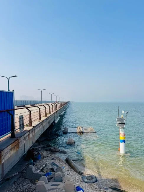
Significant Industrial User (SIU) status is defined at 40 CFR 403.3(v) and fires on any one of three triggers: (1) the facility is subject to categorical pretreatment standards; (2) it discharges 25,000 gpd or more of process wastewater; or (3) its process waste stream makes up 5% or more of the POTW's average dry-weather hydraulic or organic capacity (per EPA, 2026). A Pulaski-area EV/auto plant with a paint shop, e-coat tank, phosphate conversion coating line, or battery cell wash station will almost always meet trigger (1) through 40 CFR Part 433 (metal finishing), so SIU status is automatic and the heavier monitoring/reporting bar attaches on day one (per EPA, 2026).
Four paperwork obligations cover the bulk of the SIU compliance surface, and the one most often missing during enforcement actions is the slug load control plan. (1) Baseline Monitoring Report (BMR): required at categorical standard promulgation or at new-discharge startup, the BMR establishes the pollutant envelope every later compliance report measures against (per EPA, 2026). (2) 90-day compliance reports under 40 CFR 403.12: SIUs report on a defined schedule, hold a written control mechanism from the POTW, and submit to routine POTW inspections and sampling (per EPA, 2026). (3) Slug load control plan under 40 CFR 403.8(f): combines equalization capacity, flow and pH monitoring, and written batch-release procedures (per EPA, 2026). (4) Annual review and periodic reevaluation of local limits by the POTW under 40 CFR 403.5(c).
The slug load control plan is the deliverable that fails most Pulaski-area inspections. A slug of nickel-bearing electrolyte from a battery line, or a LiPF₆-bearing washwater slug from a cell assembly station, that reaches the collection system without a written control plan is a standalone violation independent of any numeric exceedance (per EPA, 2026). For context on the broader compliance stack applied to a similar industrial corridor, see this pretreatment compliance framework for metals plants in a neighboring Arkansas corridor.
Source-by-Source: The Five Waste Streams That Drive Pulaski Plant Design
Five source streams dominate the wastewater envelope at a Pulaski-area EV/auto plant, and each one points to a different controlling unit operation. Generic trains fail because they do not separate these streams before they recombine downstream.
| Stream | Key parameters (incoming) | Binding pollutant | Controlling unit operation |
|---|---|---|---|
| E-coat / electrodeposition rinsewater | Dissolved Ni, Zn 5–50 mg/L each; TDS 1,000–5,000 mg/L; anionic paint solids | Dissolved metals (Part 433) | Chemical precipitation + clarifier |
| Phosphate conversion rinsewater | Total P 20–80 mg/L; dissolved Fe, Zn 10–100 mg/L | Phosphorus, dissolved metals | Chemical precipitation (pH-controlled) |
| Stamping / machining lubricants | O&G 500–5,000 mg/L; TSS 500–3,000 mg/L | Emulsified FOG | DAF as front-end separation |
| Battery cell / pack assembly effluent | LiPF₆ and carbonate solvent traces; Ni/Co-bearing precursor washwater; DI blowdown | Fluoride, Li, Ni, Co | Dedicated stainless collection + separate precipitation |
| Coolant blowdown, parts-washer, floor wash | High-COD/low-metals coolant; pH 4–11 swings; TSS 200–1,500 mg/L | BOD/COD, pH excursions | Equalization + PLC-controlled neutralization; biological polishing or offsite recycling for coolant |
The phosphate conversion stream is the primary driver for the chemical precipitation stage and explains why phosphorus removal from auto plant wastewater is a recurring compliance problem (per HydropureWater, 2026). The stamping and machining lubricant streams are the reason DAF sits at the front of nearly every auto plant train: incoming emulsified oil of 500–5,000 mg/L will not gravity-separate cleanly, and free oil above the local 50–100 mg/L O&G limit fails without a dedicated FOG stage (per HydropureWater, 2026). The battery cell stream is the EV-specific addition: lithium-ion electrolyte traces (LiPF₆, carbonate solvents), nickel/cobalt precursor washwater, and deionized-water blowdown push the design toward dedicated stainless collection and a separate precipitation stage, since fluoride and lithium both create downstream problems at the receiving POTW. Coolant blowdown and parts-washer effluent carry high COD with low metals and are frequently routed through biological polishing or offsite recycling rather than discharged to sewer, because their BOD load is high relative to their volume (per HydropureWater, 2026). For specific guidance on nickel-bearing streams, see nickel removal from EV/auto wastewater.
The EQ-DAF-Clarifier Train That Hits Pulaski's Local Limits
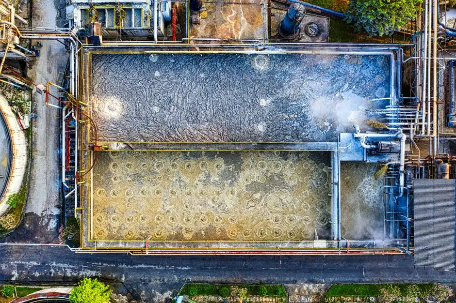
Five stages, in roughly this order, handle the vast majority of Pulaski-area EV/auto streams that go to a POTW. Not every plant needs all five; the right subset is a function of the controlling pollutant from the source table above.
| Stage | Unit operation | Design parameter | Pollutants controlled | Citations |
|---|---|---|---|---|
| 1 | Equalization basin (preceded by headworks) | 8–24 h retention; pH/flow dampening | Slug loads, pH swings, rag/solids | 403.5(a); 403.8(f) |
| 2 | PLC-controlled pH adjustment and emulsion breaking | Skid with acid/caustic, coagulant, polymer | Strong acid/caustic; emulsified O&G | 403.5(b); local pH limit |
| 3 | Dissolved air flotation (DAF) | 4–300 m³/h; micro-bubble; auto-skim | Free and emulsified O&G; bulk TSS | Local O&G cap; categorical |
| 4 | Chemical precipitation + lamella clarifier | Surface loading 20–40 m/h | Dissolved metals; residual TSS | Part 433; local metals limit |
| 5 (optional) | MBR biological polishing | PVDF 0.1 μm; ~60% smaller footprint vs. CAS | BOD/COD; residual organics | Local BOD/COD cap |
| Sludge | Plate and frame filter press | Cake to 25–35% DS | Metals-bearing solids | RCRA / CWA §405 disposal |
Stage 1 — Equalization basin. Sized for 8–24 hours of batch retention; dampens pH, flow, and concentration swings before downstream unit operations see them. Equalization is the lowest-cost insurance against pass-through events and is the most common root cause of failed compliance when it is undersized (per HydropureWater, 2026). A rotary bar screen for headworks protection typically precedes the basin to keep rags and shop debris out of downstream pumps.
Stage 2 — PLC-controlled pH adjustment and emulsion breaking. Brings strong acid/caustic batches into the 6–9 pH band required by 40 CFR 403.5(b) and the local limit, and conditions emulsified oils so the DAF can remove them. A PLC-controlled chemical dosing skid is the standard hardware.
Stage 3 — Dissolved air flotation. Operating at 4–300 m³/h with micro-bubble technology and automatic skimming, DAF removes free and emulsified oil and grease plus a large fraction of TSS in a single step. A DAF system for FOG and TSS removal is the most common first physical separation on auto-plant trains (per HydropureWater, 2026).
Stage 4 — Chemical precipitation with lamella clarifier. Coagulant/flocculant dosing followed by a lamella clarifier for metals precipitation at 20–40 m/h surface loading cuts dissolved metals into the 1–3 mg/L local band while reducing chemical consumption up to 30% versus conventional clarifiers (per HydropureWater, 2026).
Stage 5 — Biological polishing (MBR). Optional, justified when the local POTW caps BOD/COD aggressively or when the plant is moving toward reuse. PVDF membranes at 0.1 μm deliver near-reuse quality effluent at roughly 60% smaller footprint than conventional activated sludge (per HydropureWater, 2026). An MBR for biological polishing of EV/auto wastewater is the right framing when reuse or tight BOD caps apply.
Sludge handling. A filter press for metals-bearing auto plant sludge sits at the back end and addresses the disposal liability most often overlooked in early scoping.
DAF, Lamella, or MBR: Choosing the Right Stack for Pulaski's Envelope
The honest framing is "how much headroom do you need, and for how many years," not "which is better." Three unit operations cover the choice space for most Pulaski-area plants, and the right answer is a function of the controlling pollutant and the local POTW envelope.
DAF is the right first physical separation when FOG exceeds 200 mg/L or TSS is above 300 mg/L; this covers most stamping, machining, and parts-washer streams at Pulaski-area plants. A DAF system for FOG and TSS removal is the default front end, sized at 4–300 m³/h with micro-bubble technology and automatic skimming (per HydropureWater, 2026).
Lamella clarifier is the right second stage when the binding constraint is dissolved metals or total suspended solids post-precipitation. Surface loading of 20–40 m/h and up to 30% chemical savings versus conventional clarifiers is the economic case (per HydropureWater, 2026). The lamella clarifier for metals precipitation slots in after DAF and chemical dosing.
MBR is justified only when the local POTW caps BOD/COD aggressively or when the plant is moving toward water reuse; otherwise the activated-sludge step adds capex and operating cost without buying compliance headroom. An MBR for biological polishing of EV/auto wastewater belongs in the scope only when reuse or a tight BOD cap is in play. For the head-to-head decision logic, see DAF vs clarifier selection for transportation equipment plants.
Practical scoping rule: DAF-plus-lamella is the lower-capex baseline for FOG, TSS, and dissolved metals; MBR is the lower-footprint, higher-OoR option for BOD polishing and reuse. Engineer the train to 20–30% below today's local limit so the next 403.5(c) reevaluation does not force a retrofit (per HydropureWater, 2026).
Frequently Asked Questions
Which 40 CFR subparts bind EV/auto plants near Pulaski?
40 CFR Part 433 (metal finishing) governs e-coat, electrodeposition, phosphate conversion coating, and body-in-white rinsewater, and applies to any Pulaski-area plant with a paint shop or e-coat tank (per EPA, 2026). 40 CFR Part 444 covers foundry washwater, and 40 CFR Part 419 covers petroleum-derived stamping and machining lubricants. Confirm current numeric values in 40 CFR rather than relying on memory, because EPA revises subparts on a multi-year cycle.
What are the representative local POTW limits near Pulaski?
Representative small-municipality POTW pretreatment envelopes run pH 6–9, oil and grease 50–100 mg/L, TSS 200–300 mg/L, and total metals 1–3 mg/L per parameter (per EPA, 2026). Confirm against the plant's actual control mechanism before scoping equipment, because the local limit is frequently the binding constraint and may tighten on a multi-year reevaluation cycle under 40 CFR 403.5(c).
When is MBR justified for a Pulaski EV/auto plant?
MBR is justified only when the local POTW caps BOD/COD aggressively or when the plant is moving toward water reuse; otherwise the activated-sludge step adds capex and operating cost without buying compliance headroom (per HydropureWater, 2026). A DAF-plus-lamella train is the lower-capex baseline for FOG, TSS, and dissolved metals; MBR is the lower-footprint, higher-OoR option for BOD polishing and reuse.
What is the slug load control plan and why does it fail inspections?
The slug load control plan under 40 CFR 403.8(f) combines equalization capacity, flow and pH monitoring, and written batch-release procedures (per EPA, 2026). A slug of nickel-bearing electrolyte or LiPF₆-bearing washwater that reaches the collection system without a written control plan is a standalone violation, independent of any numeric exceedance, and is the documentation gap that fails most Pulaski-area inspections.