The Three-Layer Regulatory Ceiling Fabs Must Clear
Semiconductor fabs discharging to a US POTW design to a three-layer regulatory ceiling: the EPA Industrial Pretreatment Program at 40 CFR Part 403, the semiconductor categorical effluent standard at 40 CFR Part 413, and the receiving POTW's local Sewer Use Ordinance. The categorical floor in Part 413 is the EPA's semiconductor-specific limit, the general IPP in Part 403 layers the prohibition on pass-through, interference, and sludge contamination on top of it, and the SUO adds the third, often stricter, ceiling tied to downstream headworks tolerance. Engineering practice is to design to the strictest of the three, and in practice the local SUO almost always wins because the receiving POTW's biomass and headworks tolerance is the binding constraint, not the categorical floor (per EPA 40 CFR 403; 40 CFR 413). Variability across US POTWs is a real engineering risk: a fab that clears the categorical floor can still fail a small-POTW local limit, so the SUO reading is a precondition to equipment sizing (openRxiv, 2023). Step one on any project is therefore reading the receiving POTW's SUO and most-recent IPP discharge permit line by line before any pump is specified. The paper trail that closes the loop is the 40 CFR 403.12 recordkeeping rule: 3-year retention of monitoring data, calibration logs, SOPs, and Discharge Monitoring Reports. The POTW inspects both the hardware and the paperwork during routine site visits, and missing records are one of the cleanest paths into Significant Non-Compliance status during a permit cycle. Equipment decisions made now must also perform across the 5-year IPP permit cycle — and ideally across two cycles — which sets the capex payback window the CFO will want to see later.
Foundry vs. Power Discrete: How the Wastewater Signatures Differ
The same four-stage train serves both fab types, but the segregation and dose schedule diverge sharply. Foundry lines are dominated by HF and NH₄F wet-etch chemistries that push influent fluoride into the 50–500 mg/L band, with CMP slurry contributing Cu, Ni, and Co loadings that must land ≤ 1–3 mg/L individual and ≤ 5 mg/L combined at the SUO, and TMAH developer drains adding 100–200 mg/L organics plus an NH₃-N ceiling near 50 mg/L at the receiving POTW. Power discrete lines (SiC, GaN, IGBT) often run lower fluoride but heavier organic-solvent loads from dicing, back-grinding, and die-attach; GaN MOCVD tool drains additionally carry NH₃ and metalorganic precursors that complicate biological treatment. The practical segregation consequence: a foundry typically needs three headers — fluoride, metals, and TMAH — while a power discrete line often needs a fourth segregated header for organic/solvent streams before any chemistry is dosed. Combining streams forces a compromise pH window, because fluoride precipitates efficiently only at pH 6–8, metal hydroxides at pH 9–10.5, and TMAH biodegradation runs fastest outside the fluoride window — meaning the operator either overdoses reagent or accepts a slip on one parameter. Segregation is a piping decision made at fab design time and is almost impossible to retrofit cheaply; the EPC that sketches a single combined wet-well during basis-of-design will be re-piping the building during commissioning.
The Four-Stage Train, Re-anchored to Each Fab Sub-Stream
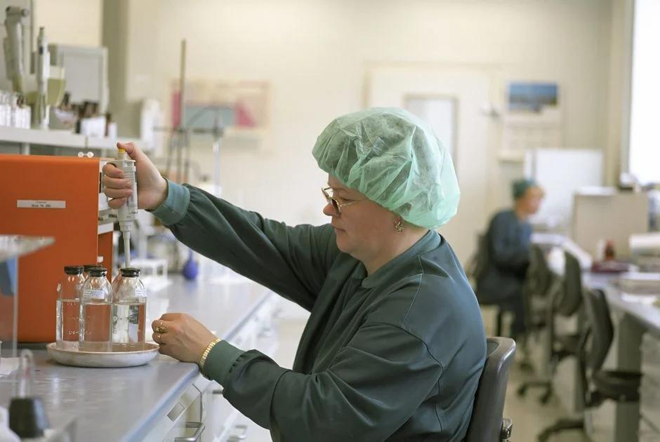
The canonical train is segregation → precipitation → solids separation → polishing, but each unit is bound to the specific sub-stream it receives so the P&ID and the article line up row by row.
Stage 1 — Source segregation and equalization. Three or four segregated headers as defined above feed separate wet wells; the equalization basin downstream of the recombined fluoride and metal headers is sized to absorb 3–5× daily-average swings in instantaneous fluoride load from batch wet-etch tool discharges. A rotary bar screen ahead of the dosing skid protects the metering pumps and the DAF recycle system from particulates, hair, and lint that ride in on utility-floor drains — one of the highest-ROI line items on the train and consistently missed in first-pass designs.
Stage 2 — pH neutralization and chemical precipitation. A PLC-controlled chemical dosing skid for CaCl₂ and NaOH drives the chemistry. CaCl₂ (preferred for solubility and a cleaner cake) or lime precipitates the fluoride stream as CaF₂ (Ksp ≈ 3.9 × 10⁻¹¹) at pH 6–8; NaOH or lime takes the metal stream to pH 9–10.5 for hydroxide precipitation. Specify 10:1 turndown on the metering pumps and require the skid to accept 4–20 mA flow-pacing plus pH and fluoride ISE feedback — the dose loop should hold reagent within ±5% of setpoint, which is the difference between a 15 mg/L fluoride cap and a permit excursion.
Stage 3 — Solids/liquid separation. A DAF system for fluoride and oily sub-streams handles 4–25 m/h hydraulic loading with consistent float capture on low-density CaF₂ floc. A lamella clarifier for footprint-constrained bays runs 20–40 m/h surface loading where the metal-hydroxide floc is denser and the building bay is tight. Either device delivers overflow TSS below the 30–60 mg/L SUO range when the upstream chemistry is correct.
Stage 4 — Polishing. Ion exchange polishes trace metals and hardness to single-digit µg/L when throughput is moderate (≤ 50 m³/h) and the operator is comfortable with resin regeneration cycles. An industrial RO polishing for ≥ 50% recycle delivers 75–95% recovery per pass and drops TDS and residual fluoride to non-critical-rinse or cooling-tower-makeup quality, which is also where the RO reclaim benchmarks in fab ESG reports sit.
For a deeper dig on the DAF-vs-clarifier decision itself, the DAF vs. lamella selection guide for fabs lays out the same logic against a representative Sioux Falls flow.
Parameter-to-Equipment Map: What Each Unit Must Actually Hit
This is the audit table most pretreatment narratives leave the engineer to assemble by hand. Every piece of equipment below is matched to the parameter it owns, the dose or loading rate that gets the effluent under the limit, and the instrument point that proves it.
| Sub-stream | Primary parameter(s) | Treatment target (SUO) | Unit operation | Dose / loading rate | Key instrument |
|---|---|---|---|---|---|
| Fluoride (HF / NH₄F wet-etch, post-etch clean) | F⁻ | < 15 mg/L (typical US POTW) | CaCl₂ or lime precipitation, pH 6–8 | CaCl₂ dose sized to peak kg/day F⁻ mass load (not avg flow); metering pump 10:1 turndown | Fluoride ISE on combined header, pH probe |
| Metals (CMP, plating, BEOL metallization) | Cu, Ni, Co, Cr, Pb, Ag | ≤ 1–3 mg/L individual; ≤ 5 mg/L combined | NaOH/lime precipitation, pH 9–10.5 | Dose to pH setpoint; sludge recirculation to cut reagent 20–30% | On-line ICP-OES or XRF for listed metals |
| TMAH developer (photoresist, wafer clean) | TMAH, NH₃-N | TMAH 100–200 mg/L (selected POTWs); NH₃-N ~50 mg/L | Segregated biological treatment | Slug-control plan required; HRT sized to peak developer batch | On-line TOC or NH₃-N probe |
| Oily / utility floor drains | Oil & grease, TSS | Per local SUO | DAF with skimmer | 4–25 m/h hydraulic loading; coagulant ahead of saturator | TSS / O&G on-line probe |
| Polishing (reuse duty) | TDS, residual F⁻, trace metals | Reuse-quality (cooling-tower makeup or non-critical rinse) | Brackish RO (≥ 50% recycle) or ion exchange | RO 75–95% recovery per pass; IX ≤ 50 m³/h per train | Conductivity, pH, F⁻ ISE on permeate |
| Solids handling | CaF₂, metal hydroxides, CMP residue | 25–35% DS cake for off-site disposal | Plate and frame filter press (1–500 m²) | 1–4% DS feed thickened upstream | Cake moisture analyzer |
An EPC can audit a P&ID against this row by row; any unit that does not have an instrument point and a dose specification on the corresponding row has a gap that the POTW will find during the next routine inspection. For Cr(VI)-bearing streams — increasingly common in third-generation work — add a dedicated reduction and precipitation step upstream of the hydroxide stage.
DAF or Lamella: The Selection Matrix
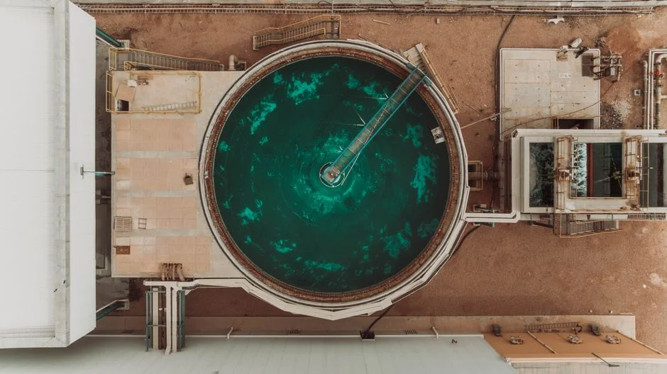
The Stage 3 decision collapses to three numbers: peak flow (m³/h), influent TSS after coagulation, and available footprint. The table below lets the engineer pick a unit before opening a vendor drawing.
| Selection driver | Pick DAF | Pick Lamella |
|---|---|---|
| Peak flow (m³/h) | 4–300 m³/h | Moderate; typically < 200 m³/h |
| Stream character | Fluoride-rich, oily, low-density floc | Denser metal-hydroxide floc, low oil |
| Surface / hydraulic loading | 4–25 m/h hydraulic | 20–40 m/h surface |
| Footprint constraint | Larger basin footprint, taller saturator room | Tight bays; inclined plates cut footprint up to 80% vs. conventional clarifier |
| Float / sludge handling | Top scrape, dry float to filter press | Bottom sludge, recirculation up to 30% to cut chemical consumption |
| Overflow TSS (when chemistry is correct) | < 30–60 mg/L | < 30–60 mg/L |
The most common pairing in a foundry fab is lamella on the metal stream (denser floc) and DAF on the fluoride stream (low-density CaF₂ with entrained fine solids that lamella lets escape). Sizing for an HF-etch DAF specifically is laid out in the HF etch DAF sizing guide. Don't skip the bar screen upstream of the dosing skid — the protection it gives the metering pumps and the DAF recycle system pays back faster than any other line item on the train.
Monitoring, Sludge, and the Permit Trail That Keeps a Fab in Compliance
Equipment alone does not keep a fab in compliance; the online instrument suite does. The minimum monitoring package for an IPP-regulated fab is a pH probe and a fluoride ion-selective electrode on the combined effluent header, plus an on-line ICP-OES or XRF unit for Cu, Ni, Cr, and any other metal the SUO specifically lists. Continuous monitoring satisfies the 24/7 expectation most POTWs now write into IPP permits and gives operations minutes of warning before a limit is exceeded, not hours. Solids from Stage 3 — CaF₂, metal hydroxides, and CMP residue — thicken to 1–4% dry solids and are dewatered in a plate and frame filter press for CaF₂ and metal-hydroxide cake (1–500 m² range) to a 25–35% DS cake for off-site hazardous-waste disposal; filtrate returns to the head of the train. The operational frame that turns hardware into a compliance program is the IPP permit cycle. A new or re-issued IPP permit runs 5 years and binds the fab to monthly Discharge Monitoring Reports submitted to the POTW, routine inspections (annually at baseline, more frequent for Significant Non-Compliance facilities), and a slug-control plan for accidental releases. Every piece of equipment on the train must be backed by an SOP and a calibration record, because the POTW will inspect both. Engineers who treat pretreatment as a permit-driven engineering program — not a black box bolted to the back of the fab — are the ones whose plants stay out of Significant Non-Compliance.
The CFO Question: Sewer vs. Off-Site Haul-Away, Worked for 10,000 m³/day
The CFO will not sign a CAPEX memo on a 5–10× ratio in the abstract. Worked for a representative 10,000 m³/day combined wastewater flow, the math is straightforward. Assumed sewer rate at a typical US POTW industrial tariff is on the order of $0.50–$2 per m³, which puts baseline sewer OPEX at roughly $1.8M–$7.3M per year. Off-site haul-away of liquid hazardous waste runs roughly 5–10× that per-m³ cost (per industry benchmarks, 2025-09), or $2.50–$20 per m³, which on the same flow becomes $9.1M–$73M per year. The implied avoided disposal cost against the haul-away case sits in the $7.5M–$65M per year band, which capitalizes a four-stage pretreatment train comfortably within a single 5-year IPP permit cycle. The capex ask is therefore framed correctly: pretreatment pays back by avoiding haul-away, not by producing revenue. The same train also unlocks ≥ 50% recycle via RO, which compounds the savings through reduced fresh intake and lower POTW volume charges — a number that dovetails directly with the electronics wastewater treatment CAPEX breakdown benchmarks and the ESG reclaim targets.
Frequently Asked Questions
What regulations govern semiconductor fab discharge to a POTW in the US?
US fabs operate under the EPA Industrial Pretreatment Program at 40 CFR Part 403, the semiconductor categorical effluent standard at 40 CFR Part 413, and the receiving POTW's local Sewer Use Ordinance. The strictest of the three governs, and in practice the local SUO almost always wins (per EPA 40 CFR 403 and 40 CFR 413). Implication: read the SUO before sizing any equipment.
How is fluoride removed from fab wastewater to meet sewer limits?
Fluoride is precipitated as CaF₂ using calcium chloride or lime at pH 6–8, with a PLC-controlled dosing skid holding reagent within ±5% of setpoint via fluoride ISE feedback, typically landing effluent below 15 mg/L. Implication: size the CaCl₂ dose to peak kg/day fluoride mass load, not average flow, and specify 10:1 turndown on the metering pumps.
What are the typical heavy-metal limits a fab must meet before sewer discharge?
Categorical and most local SUO ceilings land at ≤ 1–3 mg/L individual for Cu, Ni, Co, Cr, Pb, and Ag, and ≤ 5 mg/L combined, achieved by NaOH or lime precipitation at pH 9–10.5 followed by DAF or lamella clarification. Implication: the on-line ICP-OES or XRF analyzer on the combined header is the instrument that proves compliance 24/7.
What is the cost difference between sewer discharge and off-site haul-away for fab wastewater?
Off-site liquid hazardous-waste haul-away runs roughly 5–10× the per-m³ cost of sewer discharge (per industry benchmarks, 2025-09), which on a 10,000 m³/day fab translates to $7.5M–$65M per year of avoided disposal cost. Implication: the pretreatment train capitalizes from avoided haul-away alone, before any reuse credit from RO polishing is counted.
How long must a fab retain pretreatment monitoring records under IPP?
40 CFR 403.12 requires 3-year retention of calibration logs, SOPs, and Discharge Monitoring Reports, and the POTW inspects both hardware and paperwork during routine site visits. Implication: every piece of equipment on the train must have a current SOP and a calibration record on file, or the fab risks Significant Non-Compliance status at the next inspection.