Why HF Etch Waste Cannot Go Straight to DAF
To size a DAF for HF etch waste, you must first convert soluble fluoride to insoluble CaF2 by raising pH to 8-10 with lime or CaCl2 (lime dose 2-4× stoichiometric), then size the DAF at a hydraulic loading of 5-15 m/h with microbubbles of 40-70 µm and an air-to-solids ratio of 0.02-0.04 kg air per kg water. Materials must be HF-resistant (FRP, HDPE-lined carbon steel, EPDM).
HF and its dissociated F- ion are fully soluble in water; dissolved air flotation removes particles, not ions. Running HF rinse water through a DAF without pretreatment will give you clear effluent that still contains 500-5,000 mg/L fluoride — the bubbles have nothing to attach to. The unit operation that comes before the DAF is calcium precipitation:
Ca(OH)2 + 2F- → CaF2↓ + 2OH- or CaCl2 + 2F- → CaF2↓ + 2Cl-
CaF2 has a solubility product Ksp ≈ 3.9×10⁻¹¹, which translates to a theoretical residual F- of 8-15 mg/L when pH is held at 8-10. Real semiconductor streams arrive at 500-5,000 mg/L F-; specialty glass etching baths push 1-8% F- (10,000-80,000 mg/L) and require staged neutralization in a separate equalization tank. Everything downstream of precipitation — floc growth, bubble attachment, float skimming, sludge dewatering — assumes the fluoride is now a CaF2 particle in the 10-200 µm window. If you skip or under-dose the precipitation step, the DAF is decoration.
Step 1 — Characterize the HF Etch Stream
Before opening a sizing spreadsheet, gather the following on the actual stream, not on a P&ID assumption: flow (m³/h, including diurnal peaks), F- concentration, pH (HF streams routinely arrive at pH 1-3), temperature (HF etch baths operate 25-60 °C), co-dissolved metals (Pb, Cd, As from ITO and CdTe processes), TSS, plus nitrate, phosphate, and ammonia from post-etch cleans if the DAF effluent heads to a biological WWTP.
Temperature is the parameter most often misjudged. Viscosity drops with heat, which helps bubble rise, but Ca(OH)2 solubility also drops, and the float layer destabilizes above ~50 °C as entrained air expands and ruptures the scum. DAF feed should be cooled to <40 °C, typically with a plate heat exchanger on the equalization tank recirculation loop. Streams that co-carry Pb or Cd will re-dissolve these metals if pH drifts below 7, so the characterization table must capture the metal inventory at the same time as the fluoride.
Sampling is itself a hazard. HF samples require polyethylene bottles (glass etches), double nitrile gloves, face shield, and on-site neutralization with calcium gluconate before transport. Do not composite 24-hour samples in a glass auto-sampler.
| Stream source | Typical F- (mg/L) | Typical pH | Temperature (°C) | Co-contaminants |
|---|---|---|---|---|
| Semiconductor BOE rinse (buffered oxide etch) | 500-2,000 | 2-4 | 25-40 | NH4+, IPA, surfactants |
| Solar PV (mc-Si texturing, HIT coats) | 1,000-3,000 | 1-3 | 25-45 | HNO3, acetic acid |
| ITO / CdTe / thin-film PV | 2,000-5,000 | 2-4 | 30-50 | Pb, Cd, As, In |
| Specialty glass etching (matte etch, anti-glare) | 10,000-80,000 | <1 | 40-60 | H2SO4, HNO3, Pb, Ba |
Step 2 — Calcium-Based Fluoride Precipitation

Hold pH at 8-10. Below 8, the CaF2 Ksp is not reached and residual F- stays above 30 mg/L; above 10, Ca(OH)2 is fully dissolved but Mg(OH)2 co-precipitates and inflates sludge volume by 20-40% in streams with even modest magnesium hardness.
Stoichiometric demand is ~1.47 g Ca(OH)2 per g F- (or ~1.95 g CaCl2 per g F-). Real waste needs 2-4× stoichiometric to drive kinetics past the slow second-order regime and to overcome complexing by Al, Fe, and Si (all common in etch chemistries). For high-F streams above 5,000 mg/L, switch to CaCl2 — lime raises pH too aggressively when the acid demand is high, and runaway pH above 11 requires a second correction stage. The chloride co-ion from CaCl2 is usually acceptable for industrial discharge (no chloride limit in most jurisdictions for fab effluent), and the reaction is 1:1 molar on Ca, so dose control is straightforward.
Mixing energy matters as much as dose. Specify a rapid-mix zone with velocity gradient G > 300 s-1 for 30-60 s (an in-line static mixer is the simplest option), followed by 15-20 min of flocculation at G 50-80 s-1 to grow CaF2 nuclei into the 50-150 µm band that DAF bubbles can lift reliably. Add an anionic flocculant at 0.5-2 mg/L if natural floc is too fine — a polymer bridge is often the difference between 60% and 90% F- removal. For very high TSS streams (glass etch with suspended silica), a reactor-clarifier or lamella ahead of the DAF cuts the solids loading; for typical semiconductor rinse streams, DAF alone is sufficient. A 2026 cost-optimization guide to chemical dosing in wastewater walks through how to trim the 2-4× factor toward 2.0× once the stream is stable.
Step 3 — Size the DAF Hydraulically
Once precipitation has converted F- to a defined CaF2 particle load, hydraulic sizing is a surface-area problem. The hydraulic loading rate (HLR) for HF/CaF2 service is 5-15 m/h — markedly lower than the 15-25 m/h used for oily or food DAF, because CaF2 flocs sit at 2.5-3.0 g/cm3 (denser than oil droplets at ~0.9 g/cm3) and tend to drop out of the bubble-floc matrix if residence time is too short. Per published floc-density work (CRC Press, The Role of Floc Size and Density in Dissolved Air Flotation and Sedimentation), denser flocs require either larger bubbles or longer contact zones; lowering HLR achieves the latter without re-engineering the saturator.
Worked example: a 30 m³/h HF etch waste stream at 10 m/h HLR needs 3 m² of effective flotation surface. Add the saturator recycle — typically 20-30% of forward flow, returning at 5-6 bar and flashing to atmospheric — and the actual hydraulic load on the cell rises to 1.2-1.3× influent. So design for ~3.6-3.9 m² of cell area to keep the rated HLR after recycle is mixed in.
Specify a contact zone of 2-4 minutes (for bubble-particle attachment under controlled turbulence) and a separation zone of 15-25 minutes (for float rise and clarified water collection through bottom-laid launders). Total tank depth 1.5-2.5 m; shallower tanks (<1.2 m) lose float-layer stability when CaF2 is the dominant float because the scum has nowhere to compress. Add a 10-20% sizing margin — HF etch lines are batch-driven, not steady-state, and an oversized pump or a mis-timed rinse dump can double the hourly flow for 10-15 minutes.
Step 4 — Set the Air-to-Solids and Bubble Size
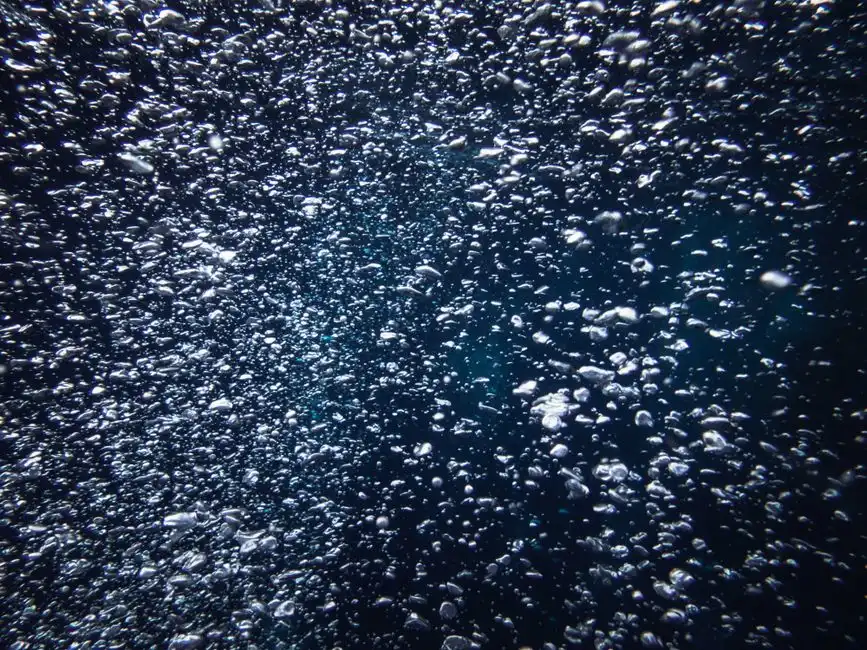
Target microbubble diameter is 40-70 µm. Smaller bubbles attach to smaller CaF2 flocs but push the saturator pressure and recycle ratio up; larger bubbles (>100 µm) rise too fast for efficient attachment in a 2-4 min contact zone. Most HF service runs at 50-60 µm median bubble size, produced from a 6 bar saturator with 20-30% recycle.
The air-to-solids (A/S) ratio for CaF2-loaded streams is 0.02-0.04 kg air per kg water — higher than the 0.005-0.015 used in oily DAF, because CaF2 flocs are denser and need more buoyancy lift per unit mass. Calculate saturator air demand as A/S × CaF2 solids load (kg/h) ÷ air density at NTP, then size the compressor with a 1.5× safety margin for the diurnal peaks noted in Step 1. Saturator residence time of 2-4 minutes at 6 bar dissolves enough air for the typical recycle ratio; a level control valve on the saturator and a pressure-relief path back to the compressor intake are both mandatory.
Use an inline nozzle or orifice-plate microbubble generator, not a packed-media saturator. Packed media fouls within weeks in HF service as residual precipitates plate out on the packing. Nozzle-type generators are also easier to clean in place with dilute HCl between maintenance windows. The dissolved air flotation system for HF etch waste uses a recirculation-loop saturator in this configuration.
Step 5 — Materials of Construction and HF Safety
Specify FRP tanks (vinyl ester or bisphenol-A resin, not polyester), HDPE-lined carbon steel, or solid polypropylene. 304/316 stainless steel fails rapidly in HF service: chloride plus fluoride attacks grain boundaries, and pitting shows up within 3-6 months on anything downstream of the precipitation stage. Gaskets must be EPDM or Viton (FKM); standard NBR swells and loses seal force in fluoride solutions, especially above 40 °C. Skimmer blades should be HDPE or PP; polyurethane softens and scores on hot CaF2 float.
Safety interlocks are not optional. HF service requires a calcium gluconate gel station at the DAF platform, an eyewash within 10 m, and a pH interlock that auto-shuts lime dosing if pH drops below 7 — otherwise an under-dosed slug of acid can evolve HF vapor into the workspace. pH probes must be double-junction with HF-resistant reference (standard single-junction probes fail within days as fluoride attacks the ceramic frit). Fluoride measurement uses an ISE with TISAB buffer, calibrated daily; total ionic strength adjustment is non-negotiable on etch streams that carry 1,000-5,000 mg/L dissolved solids.
Step 6 — Float Handling and 2026 Discharge Compliance
Float solids come off the DAF skimmer at 3-6% dry solids (DS) — a thin, gritty slurry that is mostly CaF2 with co-precipitated metal hydroxides. Route it to a plate-and-frame filter press for CaF2 sludge (or a screw press for smaller flows) to reach 25-35% DS cake. Cake is non-hazardous in most jurisdictions because the parent F- is locked in the CaF2 lattice, but the TCLP leachate test should still be run during commissioning to confirm local landfill acceptance.
Discharge compliance in 2026 sits in a tight band. China GB 8978-1996 sets F- <10 mg/L for surface water discharge. EU industrial discharge permits typically require F- <15 mg/L. The US EPA drinking water MCL of 4 mg/L applies only if the DAF effluent is being routed to a reuse system (UPW feed, cooling tower make-up). The DAF + lime stage alone achieves 8-15 mg/L F-, which clears the EU and most Chinese permits but not a reuse envelope. Polishing with ion exchange or RO is needed only for reuse; a useful rule of thumb is that if the next step is biological treatment, the DAF effluent is already fit-for-purpose. Where reuse is the target, the sizing question shifts to ZLD; see the 2026 ZLD sizing guide for curtain water for the parallel framework (same mass-balance logic, different contaminants).
Routine monitoring: daily F-, pH, TSS on DAF influent and effluent; weekly fluoride mass balance across the precipitation stage to confirm lime dose is not drifting (a 10% drift in upstream F- concentration is common when etch bath recipes change).
Design Parameter Summary for DAF on HF Etch Waste
| Parameter | Value | Units | Basis |
|---|---|---|---|
| Precipitation pH | 8-10 | — | CaF2 Ksp window |
| Lime dose | 2-4× stoich (1.47 g Ca(OH)2/g F- stoich) | g/g | Kinetic + complexing margin |
| Rapid mix G | >300 | s-1 | 30-60 s contact |
| Flocculation G | 50-80 | s-1 | 15-20 min residence |
| Anionic flocculant | 0.5-2 | mg/L | Polymer aid if natural floc fine |
| DAF feed temperature | <40 | °C | Float stability |
| Hydraulic loading rate | 5-15 | m/h | Dense CaF2 floc |
| Recycle ratio | 20-30 | % of forward flow | Saturator return |
| Saturator pressure | 5-7 (typ. 6) | bar | Air dissolution |
| Microbubble diameter | 40-70 | µm | Inline nozzle generator |
| Air-to-solids (A/S) | 0.02-0.04 | kg air / kg water | Dense floc lift |
| Contact time | 2-4 | min | Bubble attachment |
| Separation time | 15-25 | min | Float rise + clarified water |
| Tank depth | 1.5-2.5 | m | Float-layer stability |
| Float sludge DS (skimmer) | 3-6 | % DS | Pre-dewatering |
| Filter press cake DS | 25-35 | % DS | Landfill-ready |
| Materials of construction | FRP (vinyl ester), HDPE-lined CS, PP | — | HF/Cl- resistance |
| Gaskets | EPDM or Viton | — | No NBR |
| Effluent F- (DAF + lime alone) | 8-15 | mg/L | Discharge compliance band |
Worked example restated: 30 m³/h stream, 10 m/h HLR, 25% recycle, 0.03 A/S → 3 m² effective DAF surface, 7.5 m³/h saturator recycle, 6 bar saturator, ~12 kW total connected load (compressor + recycle pump + skimmer).
Frequently Asked Questions
Can DAF remove fluoride without a precipitation step first?
No. DAF removes particles, and F- ions are fully soluble. The fluoride must first be converted to CaF2 at pH 8-10 with lime or CaCl2; otherwise the DAF effluent will still contain the original 500-5,000 mg/L F-. A properly designed DAF for HF etch waste always sits downstream of a precipitation reactor.
What is the typical fluoride residual after DAF + lime treatment?
The DAF + lime stage typically achieves 8-15 mg/L F- in the clarified effluent, governed by the CaF2 Ksp of 3.9×10⁻¹¹. This clears EU industrial discharge permits (<15 mg/L) and Chinese surface water limits (<10 mg/L) in most cases. Reuse applications requiring <4 mg/L need ion exchange or RO polishing downstream.
Why is the hydraulic loading rate lower for HF/CaF2 DAF than for oily wastewater?
CaF2 flocs have a density of 2.5-3.0 g/cm3, much higher than oil droplets at ~0.9 g/cm3. To give the bubble-floc agglomerates enough time to rise in the separation zone, hydraulic loading is held to 5-15 m/h versus 15-25 m/h in oily or food DAF. Higher HLR lets the dense floc drop out of the float layer before it can be skimmed.
Which materials of construction are safe for HF-bearing DAF service?
FRP (vinyl ester or bisphenol-A resin), HDPE-lined carbon steel, and solid polypropylene are all acceptable. 304/316 stainless steel is not — fluoride plus chloride attacks grain boundaries within 3-6 months. Gaskets should be EPDM or Viton; standard NBR swells and fails in fluoride solutions above 40 °C. Skimmer blades in HDPE or PP survive; polyurethane softens on hot streams.
How is the CaF2 float sludge dewatered?
Floated CaF2 sludge leaves the DAF skimmer at 3-6% dry solids and is dewatered to 25-35% DS cake with a plate-and-frame filter press, or to 18-25% DS with a screw press on smaller flows. The cake is non-hazardous in most jurisdictions because the fluoride is locked in the CaF2 lattice, but a TCLP leachate test during commissioning confirms local landfill acceptance.
Related Equipment
- PLC-controlled lime and CaCl2 dosing system — specifications, capacity range, and technical data