
Why Pharmaceutical Wastewater Demands a Primary Clarifier
Pharmaceutical manufacturing wastewater originates from API synthesis, fermentation, formulation, and clean-in-place operations, with strengths that swing wildly batch-to-batch—typical COD ranges 1,000–5,000 mg/L and TSS 200–1,500 mg/L depending on the synthesis route and whether the discharge is a solvent-heavy reactor dump or a dilute CIP rinse. U.S. pharmaceutical manufacturers discharging to POTWs are subject to 40 CFR Part 433 categorical pretreatment standards, which set concentration- and mass-based limits for BOD, TSS, pH, and a long list of API-specific pollutants. Plants with direct surface-water discharge must additionally meet 40 CFR Part 133 secondary treatment limits of 30 mg/L 30-day average for both TSS and BOD5 (or 35 mg/L cBOD5). EPA recognizes primary clarification as Best Practicable Technology (BPT) for raw wastewater solids and BOD reduction, as cited in Clean Water Act section 304(a)(4). Removing settleable solids before biological or membrane stages protects downstream MBR membranes, activated sludge biomass, and RO units from fouling—a critical requirement when an API campaign change can shift influent character overnight. A clarifier is non-negotiable upstream of any reuse train, and the mechanics are detailed in our primary clarifier engineering mechanics guide.
How a Primary Clarifier Works in a Pharmaceutical Plant
Primary clarification relies on gravity settling: heavier suspended solids drop to the tank floor while clarified supernatant overflows effluent weirs. Two physical configurations dominate pharmaceutical service. Rectangular tanks use traveling bridge rakes and a sloped floor to scrape settled sludge toward a hopper, suiting long, narrow headworks layouts common in API plants with sequential batch reactors. Circular tanks use a central feed well that distributes flow radially and a peripheral overflow weir, with the hopper at the cone apex. For fine API solids and excipient particulates that do not settle by gravity alone, coagulants such as ferric chloride (20–80 mg/L dose) or aluminum sulfate (50–150 mg/L) are dosed into the feed well or a dedicated flocculation zone to build settleable floc. Sludge is scraped to a hopper and pumped to dewatering at 1–3% dry solids; in formulation plants handling liquid oral dosage or cream emulsions, surface skimmers remove floating oils before they reach the effluent launder. Per wwdmag.com, under top operating conditions a primary clarifier can remove up to 65% of TSS and 35% of BOD—the same baseline applies to pharmaceutical streams when coagulant dose and SOR are tuned to handle the higher and more variable solids load.
Key Design Parameters for Pharmaceutical Service
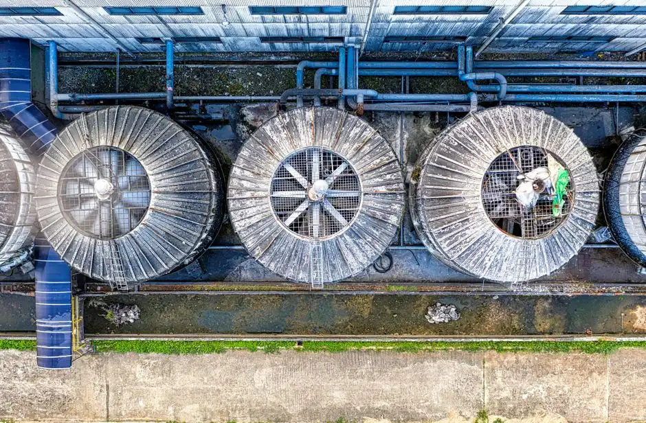
Sizing a clarifier for API, formulation, or biotech wastewater requires operating at the conservative end of the municipal design envelope. The table below summarizes the parameter set a process engineer should carry into a P&ID review or vendor RFQ.
| Parameter | Pharmaceutical Design Range | Notes |
|---|---|---|
| Surface overflow rate (SOR) | 30–50 m³/m²/day | Lower than municipal 40–60 range to absorb batch peaks |
| Hydraulic detention time | 1.5–2.5 h | Buffers against short-duration reactor dumps |
| Weir loading | ≤ 250 m³/m/day | Minimizes short-circuiting and scum carryover |
| Sidewater depth | 3.0–4.5 m | Deeper tanks improve sludge compaction |
| Underflow solids | 1–3% | Hopper geometry set for 2% typical, 3% peak |
| Coagulant dose | FeCl₃ 20–80 mg/L; alum 50–150 mg/L | Fed via a HydropureWater automatic chemical dosing system tied to flow |
| Materials of construction | 304/316L SS contact surfaces; FRP covers | SS handles solvent corrosion; FRP covers contain VOCs |
| Skimmer / oil zone | Dedicated surface removal | Mandatory for formulation lines with emulsions |
Operate the unit at 50–70% of design SOR to retain reserve capacity for future line additions, and require covered tanks with chemical scrubbers on any stream that carries fermentation off-gas or solvent vapors.
Matching Clarifier Type to Pharmaceutical Process Streams
Configuration choice follows the upstream stream character, not plant preference. The matrix below maps the four most common pharmaceutical stream types to the clarifier geometry that handles them most reliably.
| Pharmaceutical Stream | Typical Character | Recommended Clarifier | Key Design Adders |
|---|---|---|---|
| API synthesis | High TSS, intermittent solvent slugs | Rectangular with traveling rake | Equalization basin upstream; FRP cover; explosion-proof sludge pumps |
| Formulation & packaging | Emulsified oils, low-to-moderate TSS, FOG 50–500 mg/L | Circular with central feed well and skimmer | Surface skimmer; pH trim; 316L SS contact parts |
| Biotech fermentation effluent | High suspended biomass, soluble APIs, variable BOD | Circular with steeper cone, polymer-aided flocculation | Polymer dosing zone; covered tank; H₂S scrubber |
| Small-footprint retrofit | Any stream, footprint-constrained | Lamella inclined-plate clarifier | Plate pack at 55–60°; sludge cone under plate pack |
Circular clarifiers suit chemical coagulant dosing because the central well creates a defined flocculation zone where coagulant and wastewater mix under controlled hydraulic residence time before the flow enters the settling zone.
Primary Clarifier vs DAF vs Lamella for Pharmaceutical Pretreatment
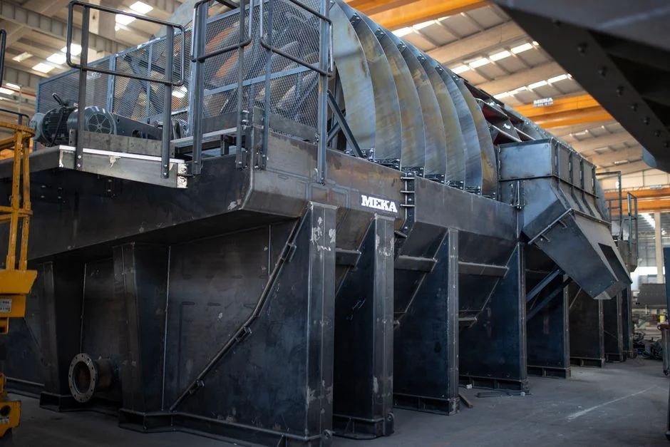
The technology choice for pharmaceutical headworks often involves stacking units: primary clarifier for bulk settleable solids, DAF for emulsified FOG, and lamella as a polishing or footprint-constrained stage. The comparison below frames the trade-offs engineers defend in a CAPEX meeting.
| Criterion | Conventional Primary Clarifier | DAF | Lamella Clarifier |
|---|---|---|---|
| Best influent | High TSS, settleable solids (API synthesis) | Emulsified oils, FOG, low-density particulates | Moderate TSS, tight footprint retrofits |
| TSS removal | 50–65% | 60–90% with coagulant | 50–80% |
| FOG removal | Limited (skimmer handles floatables only) | 95%+ (HydropureWater field data, 2026) | Limited |
| Effective SOR | 30–50 m³/m²/day | 5–25 m/h hydraulic | 20–40 m/h (HydropureWater spec, 2026) |
| Footprint | Largest | Moderate | 60–80% smaller than conventional |
| Relative CAPEX (50–200 m³/h) | USD 1–4 M installed (wwdmag.com, 2025) | Fraction of clarifier, but with air system | Fraction of clarifier, skid-mounted |
A new industrial primary clarifier runs into the millions of dollars, dominated by stainless contact parts and explosion-proof sludge pumps; a skid-mounted DAF or lamella package is typically a fraction of that for the same flow. For a deeper head-to-head on the alternatives side, see the DAF vs alternatives selection guide, and for the polishing side of a reuse train, the pharmaceutical brackish water RO engineering guide.
Operating Challenges and Smart Controls
Batch variability is the dominant operational headache in API plants: a single reactor dump can double hydraulic load for an hour, and the same line can run a low-strength fermentation broth one week and a high-strength synthesis slurry the next. Equalization upstream is a prerequisite, and the clarifier feed pump station should be sized for 2× the average batch flow. Floating scum and odorous sulfides from fermentation off-gas require covered tanks and chemical scrubbers. Recalcitrant APIs and antibiotic residues in the influent will not be removed by sedimentation—the clarifier only addresses the suspended fraction, so dissolved API load passes through to biological or advanced oxidation stages. Hybrid ANN modeling (Rustum & Adeloye, 2009) demonstrated that machine learning can predict clarifier effluent BOD5 from operating data, enabling proactive control rather than reactive sludge dumping. Standard instrumentation should include online TSS and pH on the clarifier feed, magnetic flow metering on the sludge line, and a sludge blanket level detector on the hopper to prevent solids washout during peak flow events.
Compliance and Cost Outlook for 2026

Before finalizing any clarifier design, confirm the plant's regulatory subcategory under 40 CFR Part 433—subpart 433.11 covers fermentation products, 433.12 covers synthesis, and additional subparts cover formulation, packaging, and research. Direct-discharge plants then layer 40 CFR Part 133 secondary limits (30 mg/L TSS and BOD5, 30-day average) on top of the categorical standards, which creates a tighter envelope than the secondary standard alone would require. For 2026 CAPEX framing, a stainless-clad industrial primary clarifier sized for 50–200 m³/h typically falls in the USD 1–4 million installed range (wwdmag.com, 2025), with the line-item drivers being 316L stainless contact surfaces, FRP covers, and ATEX-rated sludge pumps. Operate the unit at 50–70% of design SOR so future line additions do not require a second tank, and bundle the clarifier with a downstream HydropureWater MBR membrane bioreactor or a DAF polishing stage such as the HydropureWater DAF system to keep the reuse train within RO fouling limits.
Frequently Asked Questions
What influent COD and TSS range should I use to size a primary clarifier for an API plant?
Use COD 1,000–5,000 mg/L and TSS 200–1,500 mg/L for typical API synthesis and formulation streams, and design the equalization basin for at least 8 hours of batch buffering before the clarifier feed. Validate with composite sampling across at least three production campaigns, since batch-to-batch swings can exceed 3× the average.
Does a primary clarifier remove dissolved APIs or antibiotics?
No. Primary clarification is a physical settling process and only addresses the suspended fraction—typically 50–65% of TSS and 25–35% of BOD under pharmaceutical operating conditions. Dissolved APIs, solvents, and antibiotic residues pass through and must be handled by downstream biological treatment, advanced oxidation, or activated carbon.
When should I choose a lamella clarifier over a conventional circular or rectangular unit?
Choose lamella when footprint is constrained or when the unit is a polishing stage downstream of a DAF or equalization tank. Lamella inclined plates boost effective SOR to 20–40 m/h (HydropureWater spec, 2026) and cut footprint 60–80% versus a conventional clarifier, but lamella is less tolerant of high-TSS slugs and grit than a conventional scraped tank.
What is the 40 CFR Part 433 subcategory that applies to my plant?
Subpart 433.11 covers fermentation products, 433.12 covers synthesis, 433.13 covers formulation, 433.14 covers packaging, and 433.15 covers research. Each subcategory carries its own categorical pretreatment limits, so the subcategory determination drives the clarifier effluent target before the secondary limits in 40 CFR Part 133 are layered on.
Related Equipment
- HydropureWater lamella clarifier — specifications, capacity range, and technical data