
What PAC Dosing Design Criteria Mean for Industrial Skids
PAC dosing design criteria convert a jar-test mg/L setpoint into a working industrial skid covering feed characterization, storage, metering, injection hydraulics, and closed-loop control. A defensible 2026 datasheet cites ASME B73.1, ANSI/HI 9.6.6, API 650, and ISA-88 batch concepts with measurable numbers for each item. Anything less is pool-feeder analogy, not plant engineering.
Pool-style hardware does not scale to plant duty. According to PWTAG Technical Note 24 (Feb 2014), pool PAC is dosed at about 0.1 ml/m³ of circulation flow from a peristaltic pump, with at least 10 seconds of contact at ≤1.5 m/s velocity. That fits a steady 225 m³/h pool circuit. An industrial clarifier at 5–500 m³/h sees 2–3× flow swings and alkalinity drift. The skid must absorb that variability with flow pacing plus streaming-current trim, not a drum and a squeeze-tube pump.
Overdosing reverses colloidal charge and yields a cloudy supernatant that defeats the clarifier. Underdosing passes turbidity downstream and shortens filter runtimes. The five criteria below are what a process engineer can hand to procurement without rewriting the package later.
Step 1 — Establish the Target Dose with Jar Testing
Jar testing is the only method that ties dose to a specific raw water, and it is the setpoint the PLC will multiply by flow. The bench procedure is standardized: 1 L beakers and six to eight dose points bracketing the expected band. Rapid mix at 120–150 rpm for 1 min, then slow mix at 30 rpm for 20 min, then settle 30 min. Measure supernatant turbidity, residual color, and residual aluminium. Use a jar test procedure that is repeatable across operators — the dose is only as defensible as the bench technique behind it.
For most industrial wastewaters the expected band is 5–150 mg/L of commercial PAC liquid. In low-alkalinity drinking water, a 2025 GA-optimized full-scale study narrowed the practical range to 4–12 ppm (MDPI Computation, 2025-08). pH should sit in the 5.5–8.5 window for the dose to be effective. Decision rule: pick the lowest dose that clears the turbidity/color target without leaving a positive streaming-current reading at the outlet. Overdosing symptoms show up first as sticky flocs, floating sludge, and a milky supernatant.
Most plants we size for industrial raw water run jar-test setpoints near the lower third of the 5–150 mg/L band when turbidity is moderate and alkalinity is stable. The output of jar testing is a single number — mg/L — that becomes the dosing setpoint. The PLC multiplies that number by measured flow to command the pump, so any bench error propagates linearly into chemical spend.
How do you prepare PAC for dosing?
Commercial liquid PAC is used as delivered for industrial metering; do not dilute it in the bulk or day tank. According to PWTAG (2014), dilution with water forms an irreversible gel and ruins the batch — that standing warning still applies in 2026. Typical commercial grades are 10–17% Al₂O₃ (10% w/w is common in published full-scale work). Transfer neat product to the day tank, keep a low-speed mixer for uniformity, and let the metering pump draw from a flooded suction. For applications such as pac for egcs dosing, the same no-dilution rule applies even when the process chemistry differs from clarifier coagulation.
Step 2 — Size the Storage and Day Tanks
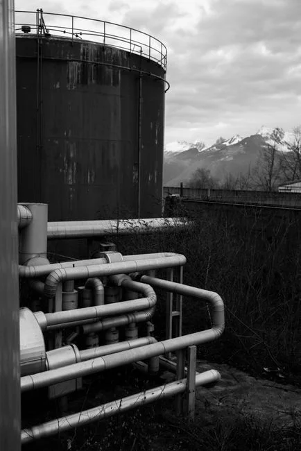
Storage tank sizing for an industrial polyaluminum chloride dosing skid is a 7–14 day consumption problem, not a corner-fit problem. Bulk PAC is delivered as a 10–17% Al₂O₃ liquid. The working formula is:
Tank volume (m³) = [Dose (mg/L) × Flow (m³/day) × Days] ÷ [Concentration (mg/L) × 10⁶]
For a 100 m³/h plant at 30 mg/L dose running 7 days, using 10% PAC (≈100,000 mg/L active): 30 × 2,400 × 7 ÷ 100,000 = ~5.0 m³ working volume, before any safety factor. Add 1.5–2× for the bulk tank itself, plus a day tank sized for 8–24 h of consumption with a level switch that interlocks the transfer pump.
Material selection is non-negotiable. Cross-linked polyethylene or FRP is standard. Never dilute PAC with water in the storage tank. Codes to reference on the datasheet: API 650 for atmospheric tank fabrication, and NFPA 30 for flammable-liquid storage layout where it applies. Earlier datasheets often labeled secondary containment as 110% of the largest tank under an NFPA 30 heading. NFPA 30 itself requires 100% of the largest tank. A typical packaged approach uses skid-mounted Automatic Chemical Dosing System frames that integrate the day tank, mixer, level instrumentation, and metering pump — this is the configuration most procurement teams actually order.
Step 3 — Select the Metering Pump and Piping
Pump topology is decided by flow and turndown. Peristaltic pumps win at the low end — they hit the 0.1 ml/m³ accuracy band that PWTAG specifies for pool duty and have no seals to leak. At industrial flows the workhorse is a mechanical-diaphragm coagulant metering pump with a turndown of ≥100:1 so it can ride through the 2–3× flow swings that show up in real raw water. ANSI/HI 9.6.6 is the standard to cite for reciprocating positive-displacement metering-pump performance and turndown verification. ASME B73.1 covers chemical process pumps more generally and should appear on the data sheet as a baseline reference.
Sizing equation:
Pump capacity (L/h) = [Dose (mg/L) × Flow (m³/h) ÷ PAC concentration (mg/L)] × 1000
Apply a 1.5–2× safety factor, then check that minimum pump capacity at the lowest credible flow still exceeds the dose the chemistry actually needs. A 100 m³/h plant at 30 mg/L using 10% PAC needs 30 L/h of active solution. With a 1.5× factor, specify a 45 L/h pump that can turn down to 0.45 L/h for low-flow periods — well within a 100:1 turndown envelope.
Wetted parts should be PVC, PP, or PVDF; diaphragms in EPDM or Viton. Avoid carbon steel — it corrodes and contaminates the coagulant with iron, which downstream operators will see as a sudden colour excursion. Calibration cadence: factory calibration at commissioning, then in-situ volumetric verification quarterly and after every diaphragm replacement. The table below compares pool-duty hardware against industrial-duty hardware for the same chemical.
| Parameter | Pool duty (PWTAG, S3) | Industrial duty (2026 spec) |
|---|---|---|
| Typical flow range | ≤500 m³/h, steady | 5–500 m³/h, 2–3× swing |
| Dose accuracy target | ~0.1 ml/m³ | ±5% of setpoint across turndown |
| Pump type | Peristaltic, direct from drum | Mechanical diaphragm, ANSI/HI 9.6.6 |
| Turndown ratio | 10:1 typical | ≥100:1 |
| Control | Manual stroke + flow switch | Flow-paced 4–20 mA + streaming-current trim |
| Tank | IBC / drum, no dilution | API 650 bulk + day tank, 110% containment |
| Calibration | Annual | Quarterly volumetric + post-maintenance |
An integrated automatic chemical dosing system skid pairs storage, mixing, level instruments, and the metering pump on one frame. That package is the practical way to buy the hardware and control on a single purchase order.
What belongs in a PAC dosing station?
A PAC dosing station is the packaged boundary procurement can buy as one line item. It includes bulk or IBC feed, a day tank with level switches, and a transfer-pump interlock. Add a mechanical-diaphragm metering pump, calibration column, injection quill with check valve, and a PLC panel with flow-paced 4–20 mA output. Plants running pac dosing for sbr tank service still need the same station blocks; only the setpoint logic and hydraulic tie-in change. Skip any of those blocks and field crews end up fabricating them under change order.
Step 4 — Injection Hydraulics and Contact Time

Dose accuracy is wasted if the chemical never sees the water. Injection velocity into the main process flow should stay at or below 1.5 m/s so the jet does not shoot past the reaction zone (PWTAG, 2014). Coagulation contact time needs to be at least 10 seconds in the pipe or flash-mix chamber, with an additional 30–60 seconds before any polymer is added if a flocculant aid follows. Sequence matters: PAC first, polymer second, or the polymer coats the colloids and blocks the coagulant from working.
Injection hardware is a quill or lance with a check valve to prevent backflow during pump shutdown. Place the controller sample point upstream of the injection point, but downstream of any prior chemical addition. That way the controller sees the water it is about to dose, not the water it has already dosed. For open tanks or basins where the pipe velocity is unreliable, specify a static mixer or a pumped recirculation loop sized to deliver a velocity-gradient × time (G·t) ≥ 10⁴ before the clarifier feedwell. G·t below 10⁴ is the usual reason a correctly metered dose still produces pinpoint floc that will not settle.
Secondary clarifier design criteria after coagulation still start with floc quality leaving the flash mix. Settling rate, overflow rate, and sludge blanket depth only work if the PAC dose and G·t produced a settleable floc. When buyers ask how to select a clarifier system for industrial wastewater, the honest answer is that clarifier hydraulic loading is inseparable from upstream coagulant dose control.
Step 5 — Control Architecture and Closed-Loop ROI
Open-loop flow pacing from a magflow meter with the dose set from the last jar test is the baseline. It is also the most common configuration in 2026 and the easiest to defend in a procurement review. The upgrade path is a streaming current control loop at the clarifier inlet, trimming the dose setpoint in real time as raw-water charge demand shifts. A 2025 full-scale drinking-water ANN–GA study reported a 49% cut in median PAC-related treatment cost (MDPI Computation 13(8):179, 2025-08). Color-limit compliance rose from 52% to 63%, while pH compliance stayed above 97%. That 49% is a drinking-water upper bound. Industrial buyers should pilot a streaming-current loop before scaling it plant-wide.
Minimum PLC I/O list for a defensible specification:
- Analog in (4–20 mA): flow from magflow on the raw-water line
- Analog in (4–20 mA): day-tank level
- Analog out (4–20 mA or 0–10 V): pump speed command, 0–100%
- Digital in: day-tank low-level interlock (pump inhibit on empty)
- Digital in: transfer-pump run confirmation
- Analog in (optional, closed loop): streaming-current sensor, 4–20 mA
The cost framing matters because it is the language procurement uses. For a 100 m³/h plant at 30 mg/L dose using 10% PAC solution, consumption is 30 kg/h of active product. A 10% overdose wastes ~3 kg/h continuously — that is roughly 26,000 kg/year of coagulant. At typical industrial chemical prices that pays for a streaming-current retrofit in under 12 months on chemical savings alone. That single number turns a dosing-accuracy argument into a budget line item. The same over- and under-dosing opex pattern shows up in sludge dewatering system design criteria and RO water purification design criteria.
| Control mode | Hardware | Typical dose error | Indicative payback |
|---|---|---|---|
| Open-loop, manual setpoint | Magflow + diaphragm pump | ±15–20% | Baseline |
| Open-loop, flow-paced | Magflow + 4–20 mA pump command | ±5–10% | <6 months on chemical savings |
| Closed-loop, streaming-current trim | Flow-paced + streaming-current sensor + PID | ±2–5% | ≤12 months; up to 49% cost reduction (MDPI 2025 DWTP study, S5) |
Note: payback figures are illustrative, based on a 100 m³/h plant at 30 mg/L dose with 10% PAC solution and industrial-grade coagulant pricing in 2026.
Selection Checklist Before You Issue the PO
Use this short checklist when reviewing a vendor package against plant duty:
- Jar-test dose documented in mg/L with pH window 5.5–8.5 and raw-water identity
- Bulk + day tank volumes for 7–14 days and 8–24 h respectively, with 100% largest-tank containment (plus rain where outdoor/SPCC or RCRA applies)
- Metering pump turndown ≥100:1, ANSI/HI 9.6.6 cited, PVC/PP/PVDF wetted path
- Injection velocity ≤1.5 m/s and ≥10 s contact before flocculant or clarifier feedwell
- Flow-paced 4–20 mA as baseline; streaming-current trim budgeted if raw water swings daily
- Calibration column and quarterly volumetric verification written into the O&M plan
- No water dilution of PAC anywhere in the storage or day-tank train
Who This Is For / Next Step
This specification path fits plant engineers, EPC packages, and procurement teams sizing PAC coagulation ahead of clarification or filtration on variable industrial raw water. Look elsewhere if the duty is a steady pool circuit at ~0.1 ml/m³ — PWTAG peristaltic-from-drum hardware is enough there. When you need a skid quoted against these criteria, send the flow range, jar-test dose, and tank days to the request-quote form so the package can be sized on your numbers, not catalog defaults.
Frequently Asked Questions
What is the typical PAC dose range for industrial wastewater?
Across most industrial wastewaters, commercial polyaluminum chloride is dosed at 5–150 mg/L as product, with an effective pH window of 5.5–8.5. In low-alkalinity drinking water the practical operating band is much tighter at 4–12 ppm, per a 2025 GA-optimized full-scale study (MDPI Computation, 2025-08). Always confirm with a site-specific jar test before locking the PLC setpoint.
How do you size a PAC storage tank?
Use Tank volume (m³) = [Dose × Flow × Days] ÷ [Concentration × 10⁶], then apply a 1.5–2× safety factor. A 100 m³/h plant at 30 mg/L using 10% PAC needs roughly 5 m³ of working volume per week. Design secondary containment to at least 100% of the largest tank (NFPA 30 / 40 CFR 264.193), and never dilute PAC in the storage tank — it gels (PWTAG, 2014).
Which metering pump standard applies to PAC dosing?
ANSI/HI 9.6.6 is the standard for reciprocating positive-displacement metering-pump turndown and performance verification, and should be cited on the data sheet. ASME B73.1 covers chemical process pumps more generally. Specify a turndown of ≥100:1 for industrial service, with mechanical-diaphragm or peristaltic wetted paths in PVC, PP, or PVDF.
What controls do I need on a PAC dosing skid?
At minimum: analog in for flow (4–20 mA), analog in for day-tank level, analog out for pump speed (0–100%), and a digital low-level interlock. A streaming-current sensor at the clarifier inlet can cut PAC cost by up to 49% in drinking-water service (MDPI, 2025-08). Industrial payback is typically under 12 months on chemical savings.
What happens if I overdose or underdose PAC?
Overdosing reverses the colloidal charge, producing a cloudy supernatant and increased sludge volume. Underdosing passes turbidity downstream and shortens filter runtime. Either direction drives operating cost up; a flow-paced or streaming-current-trimmed loop is the standard 2026 mitigation on variable industrial raw water.