
What Are DAF Clarifier Design Criteria?
DAF clarifier design criteria are the engineering parameters that size a dissolved air flotation unit: hydraulic loading rate of 5–25 m/h, recycle ratio of 10–50%, air-to-solids ratio of 0.005–0.060 kg air per kg solids, flocculation retention of 10–30 minutes, and float/sludge retention of 20–60 minutes.
A DAF is a physical separation unit in which 10–100 µm micro-bubbles attach to flocculated suspended solids, oil droplets, and colloidal matter and carry them to the surface as a float blanket, which a skimmer then removes. It is distinct from a gravity sedimentation clarifier, which relies on mass and Stokes-law settling rather than buoyancy. Seven core parameters govern the design: hydraulic loading rate, surface overflow rate, hydraulic retention time, recycle ratio, air-to-solids (A/S) ratio, flocculation retention time, and saturator pressure.
The design objective in 2026 industrial practice is 80–95% removal of total suspended solids (TSS), fats/oils/greases (FOG), and colloidal matter inside a flotation zone of 20–60 minutes. Where a gravity clarifier needs an hour or more of settling and a large footprint, a DAF can hit the same or better removal in a fraction of the volume. This article publishes the 2026 design ranges a process engineer needs to size, specify, and defend a DAF unit in a P&ID review or a 2026 CAPEX submission.
DAF Design Parameter Table: 2026 Engineering Ranges
The table below provides the engineering ranges for quick reference. Values are current 2026 vendor and standard-practice ranges; derive your final selection from jar tests and pilot data. For a packaged unit that meets these ranges, see a Dissolved Air Flotation (DAF) System reference design. Broader daf system design context sits on a sibling page; this article stays on numeric sizing criteria.
| Parameter | Typical 2026 Range | Units | Design Driver |
|---|---|---|---|
| Hydraulic loading rate | 5–25 | m/h | Sets tank cross-section; higher rates shrink footprint but risk short-circuiting |
| Surface overflow rate (SOR) | 5–20 | m/h | Drives effluent clarity; lower SOR = clearer effluent |
| Flotation retention (separation zone) | 20–60 | min | Drives tank volume; sized to allow full float rise |
| Flocculation retention | 10–30 | min | Pre-flocs feed so micro-bubbles can attach; too short = poor removal, too long = floc shear |
| Recycle ratio | 10–50 | % of throughput | Higher ratio improves float but increases pump and compressor energy |
| Air-to-solids (A/S) ratio | 0.005–0.060 | kg air / kg TSS | Directly controls float rise velocity and TSS removal |
| Saturator pressure | 4–6 | bar(g) | Sets dissolved air mass; below 4 bar A/S collapses, above 6 bar compressor cost spikes |
| Saturator retention | 30–60 | s | Residence time needed to fully saturate recycle water with air |
| Contact-zone retention | 1–3 | min | Mixing of pressurized recycle with flocculated feed; bubble–floc contact |
| Skimmer speed | 0.5–3 | m/min | Drives float to launder; higher speed for thicker blankets |
| Sludge bed depth | 0.3–1.0 | m | Bottom zone for non-floating heavy solids; scraped to a sump |
The contact zone typically holds 1–3 minutes and the separation zone 20–60 minutes. In a food-processing case documented by Ecologix, DAF achieved 95% oil/grease removal versus 70% for a clarifier on the same influent.
How Each Design Parameter Controls Performance

Hydraulic loading rate and surface overflow rate set the tank cross-sectional area. Above ~20 m/h, the upward drag from cross-flow starts to carry float back into the bulk liquid, and effluent TSS climbs. Below 5 m/h the unit is over-sized and capital is wasted. Most 2026 industrial packaged DAFs sit between 10 and 20 m/h on the SOR. In customary U.S. units, industrial hydraulic loading rates of 2 to 5 gallons per minute per square foot (gpm/ft²) are common, while municipal or high-density solids duties often run more conservatively at 1.5 to 3 gpm/ft².
Recycle ratio is the fraction of clarified effluent you pressurize, dissolve air into, and return to the contact zone. At 10% you run lean, which is effective for low-solids streams and modest energy budgets. At 50% you run rich, which is necessary for high TSS, high FOG, or colloidal streams where the bubble flux must be high to lift particles. The trade-off is pump and compressor power; a 50% recycle can double the air-supply operating cost versus a 20% recycle. Some older vendor sheets still cite recycle at 5% to 15% of influent flow; treat that band as a light-duty floor, not a universal target against today’s 10–50% throughput-based practice.
Air-to-solids ratio is the primary performance-defining number. It expresses the mass of air dissolved in the recycle per mass of TSS in the feed. 0.005 kg/kg is the typical minimum for light FOG streams; 0.060 kg/kg is the high-strength ceiling for thick, colloidal, or oily streams. Dropping below the minimum causes a patchy float blanket and increased effluent TSS, while pushing past the ceiling increases compressed air costs without improving removal. Texts that report 0.01–0.05 mg air per mg dry solids sit inside the same 0.005–0.060 kg/kg band used in the table above.
Flocculation retention of 10–30 minutes is required upstream of the DAF. The micro-bubbles in a DAF are 10–100 µm and can only attach to pre-formed flocs in the 50–500 µm range. Insufficient floc time leads to pin-floc and turbid effluent; excessive time causes polymers to shear the floc, collapsing removal efficiency. The automatic chemical dosing system ahead of the floc tank should be paced on flow.
Saturator pressure of 4–6 bar(g) controls the dissolved-air mass per cubic meter of recycle. Henry's-law air solubility roughly doubles between 4 and 6 bar, making saturator pressure the most efficient way to raise the A/S ratio. Below 4 bar the A/S ratio collapses; above 6 bar the compressor specific power and maintenance cost rise sharply without proportional removal gain. Equivalent English-unit guidance of 40–70 psi remains in many North American specs and overlaps the lower half of the 4–6 bar(g) band.
Separation-zone retention of 20–60 minutes drives tank volume. High-FOG streams typically require the upper end of that 20–60 minute band to allow full float rise, while light colloidal streams generally require 20–30 minutes.
Process Flow: Contact Zone, Separation Zone, and Sludge Zone
A DAF tank has three functional zones stacked along its length or height. In the contact zone, the pressurized recycle stream enters through a distribution header and mixes with the flocculated feed for 1–3 minutes; this is where 10–100 µm micro-bubbles nucleate on the flocs as the recycle drops from 4–6 bar to atmospheric. In the separation zone, the bubble-laden flocs rise as a blanket for 20–60 minutes; clarified water exits as underflow at the bottom of this zone. In the sludge zone, the small fraction of solids that do not float — typically heavy grit, metal hydroxides, or broken flocs — settles to the bottom and is scraped to a sump.
The side-stream recycle loop maintains the process. Clarified effluent leaves the separation zone, is pressurized by a recycle pump to 4–6 bar, receives air through an eductor or compressor line, then flows into a saturation tank held at 4–6 bar for 30–60 seconds. From there, the saturated recycle is piped back to the contact zone. When it discharges through a release nozzle, the pressure drop flashes dissolved air out of solution as a dense cloud of micro-bubbles. A coagulant and flocculant dosing system ahead of the floc tank is the upstream partner that determines whether the bubble–floc attachment succeeds.
Surface skimming drives the float to a launder at 0.5–3 m/min, with speed adjusted based on blanket thickness. A bottom scraper handles the sludge bed. Materials of construction in 2026 are typically carbon steel with epoxy or rubber lining for mild streams and 304/316 stainless for corrosive, high-temperature, or high-chloride feeds, such as refinery desalter effluent or textile dye-bath overflow.
How to Select the Right Clarifier System for Industrial Wastewater?
Industrial wastewater clarifier system selection starts with particle behavior, not with catalog CapEx. Map the influent into floatable FOG and colloids versus settleable grit and hydroxides, then set effluent TSS and FOG targets against the permit with a diurnal safety margin. When FOG exceeds 50 mg/L or colloids dominate, DAF hardware is the right fit; when settleable TSS exceeds about 70% of total suspended solids and FOG stays below 50 mg/L, gravity hardware wins on energy and simplicity.
Run jar tests before you lock hydraulic loading, A/S ratio, or polymer dose. Plants that skip this step usually oversize recycle pumps or chase effluent turbidity with excess chemical. For activated-sludge polishing duties that are outside this article’s scope, see the sibling note on secondary clarifier design paramter rather than forcing a DAF into a settleable biomass role.
How Do Primary, Secondary, Lamella, and DAF Options Compare?
Primary clarifiers and gravity thickener design clarifier trains remove dense settleable solids before biological or chemical stages. Secondary clarifiers settle biomass after aeration. Lamella packs raise gravity surface rate inside a smaller footprint. DAF replaces buoyancy for oil, FOG, and light colloids that will not settle in a practical HRT.
Hybrid trains are common on complex industrial feeds. Place gravity primary or a high-efficiency lamella clarifier upstream when grit and metal hydroxides dominate, then use DAF to strip residual FOG. Reverse the order when oil is the primary load and only a small settleable fraction remains. Selecting clarifier system for industrial wastewater design criteria therefore means matching each stage to the solids class it can actually remove, not stacking every technology “just in case.”
DAF vs Gravity Clarifier: When to Use Each in 2026
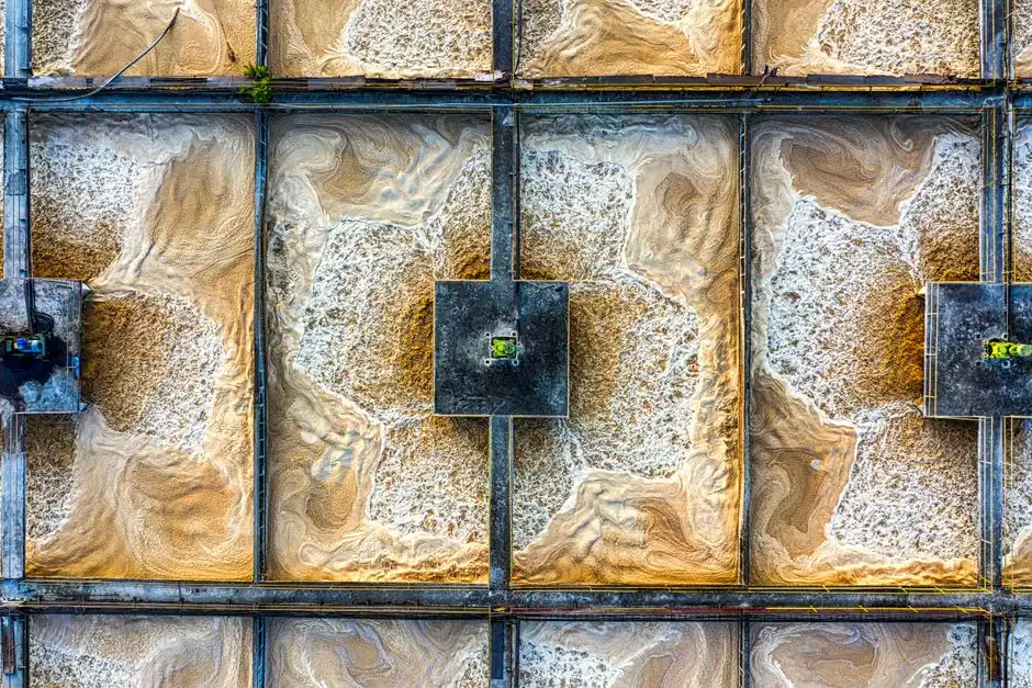
Influent characteristics, rather than capital cost alone, should drive the choice between a DAF and a gravity clarifier. The matrix below provides the data an EPC designer needs to defend a recommendation in a design review.
| Criterion | DAF | Gravity Clarifier (incl. Lamella) |
|---|---|---|
| Removal mechanism | Micro-bubble flotation (buoyancy) | Gravity sedimentation (Stokes settling) |
| Typical TSS removal | 80–95% | 50–90% |
| Typical FOG removal | 90–95% | <50% |
| Footprint | 3–5× smaller for equal loading | Large; needs long retention or lamella plates |
| CapEx | Higher (saturator, compressor, recycle pumps) | Lower (plain tank, scraper) |
| OpEx | Higher (compressed air, recycle pumping, polymer) | Lower (no compressor) |
| Best influent | Oil, FOG, colloidal, light suspended matter | Heavy settleable solids, grit, metal hydroxides |
| Reference case | Food plant: 95% FOG removal with DAF vs 70% with clarifier (Ecologix) | Mining facility: 90% solids reduction at lower cost with clarifier (Ecologix) |
Engineers can defend the selection decision with this rule: if FOG is above 50 mg/L or if colloidal material dominates, pick DAF; if settleable TSS is above 70% of total suspended solids and FOG is below 50 mg/L, pick a clarifier. Hybrid configurations are endorsed for streams that carry both — using DAF as a primary oil/FOG stripper ahead of a clarifier or a lamella polishing step for residual settleable solids.
Sizing Checklist and Compliance Footnote
Before finalizing a P&ID, verify the unit against this six-step sizing checklist:
- Characterize the influent: TSS, FOG, BOD/COD, temperature, pH, and the fraction of colloidal versus settleable solids.
- Set the target effluent TSS and FOG to the discharge limit, including a safety margin for diurnal swings.
- Choose the A/S ratio from the table above based on influent strength: 0.010–0.020 kg/kg for light streams, 0.030–0.060 kg/kg for high-FOG or high-colloid streams.
- Choose the recycle ratio: 10–20% for light streams, 30–50% for heavy or oily streams.
- Set flocculation time at 10–30 minutes based on jar tests; the automatic chemical dosing skid should pace on flow.
- Verify separation-zone volume from the chosen flotation retention (20–60 min) times the hydraulic flow, including the recycle stream.
Run jar tests on the actual wastewater before locking any design parameters, as coagulant and flocculant doses vary significantly between industries. Regulatory compliance depends on local frameworks, such as U.S. EPA 40 CFR 437 (metal finishing) or 40 CFR 419 (petroleum refining), and EU Directive 2010/75/EU (Industrial Emissions Directive). Confirm the applicable BAT-AEL with your permitting authority before sign-off.
Who This Is For / Who Should Look Elsewhere / Next Step
This guide is for plant engineers, EPC process leads, and procurement teams sizing industrial DAF for FOG-rich or colloidal wastewater. Look elsewhere if your duty is mainly settleable biomass after aeration, or if you only need sludge thickening without flotation. When jar-test data and flow rates are ready, request a packaged sizing review through our DAF design inquiry form so recycle ratio, A/S, and tank volume can be checked against your permit limits.
Frequently Asked Questions
What are the design criteria for a DAF clarifier?
DAF clarifier design is governed by hydraulic loading of 5–25 m/h, SOR of 5–20 m/h, recycle of 10–50%, A/S of 0.005–0.060 kg air per kg TSS, flocculation of 10–30 minutes, and separation retention of 20–60 minutes. Saturator pressure is typically 4–6 bar(g), or about 40–70 psi on older English-unit sheets. Contact-zone retention of 1–3 minutes supports bubble–floc attachment after jar-tested chemistry.
What is the typical air-to-solids ratio for industrial DAF?
The typical 2026 engineering range is 0.005–0.060 kg air per kg of TSS. Use 0.005–0.015 kg/kg for light FOG or low-TSS streams, 0.020–0.035 kg/kg for typical food-plant loads, and 0.030–0.060 kg/kg for high-FOG or colloidal feeds. Equivalent literature values of 0.01–0.05 mg air per mg dry solids fall inside that band. Exceeding the ceiling mainly raises compressor cost without raising removal.
What hydraulic loading rate should be used for a DAF unit?
Industrial DAF units commonly use 5–25 m/h hydraulic loading and 5–20 m/h SOR, with most packaged plants at 10–20 m/h SOR. In U.S. customary terms, 2 to 5 gpm/ft² is a frequent industrial band, while municipal or dense-solids duties often use 1.5 to 3 gpm/ft². Exceeding the rise-velocity limit causes short-circuiting and solids carryover into the clarified effluent.
When is a gravity clarifier better than a DAF system?
A gravity clarifier is better when suspended solids have specific gravity well above 1.0 and settle without bubble assistance. Choose gravity when settleable TSS is above about 70% of total TSS, FOG is below 50 mg/L, and lower OpEx matters more than footprint. Mining and metal-hydroxide streams often fit this profile; the Ecologix mining reference showed about 90% solids reduction at lower cost with a clarifier.
Can DAF and a clarifier be used together for industrial wastewater?
Yes. Series trains are standard when a feed carries both dense settleable solids and light FOG or colloids. Gravity primary or lamella stages can strip grit and hydroxides first, then DAF polishes oil and non-settleable matter—or DAF can strip FOG first when oil dominates. The order follows which solids class creates the largest permit risk, not a fixed template.