What a Constructed Wetland Is and How It Treats Wastewater
Constructed wetlands (CWs) are engineered treatment systems that use natural processes involving wetland vegetation, soils, and their associated microbial assemblages to improve water quality (per US EPA, epa.gov/wetlands/constructed-wetlands). For an industrial buyer, the practical translation is this: a lined, planted bed with controlled inlet and outlet hydraulics, designed to remove dissolved and particulate pollutants through a stacked set of physical, chemical, and biological mechanisms rather than through intensive mechanical aeration or membrane separation.
Two hydrological categories dominate current practice. Free water surface (FWS) wetlands hold exposed water above the substrate and mimic a marsh. Subsurface flow (SSF) wetlands keep water below the gravel or media surface and split into vertical flow (VF), dosed intermittently from the top, and horizontal flow (HF), fed continuously along a slight gradient (S4, ScienceDirect). Pollutants are removed through plant uptake (nitrogen, phosphorus), substrate sorption (heavy metals, phosphates), and rhizosphere microbial activity that drives nitrification, denitrification, and anaerobic sulfate reduction.
The industrial credibility of this technology rests on a 2013 Saint-Étienne/Silesian thesis that documented, for the first time, metal and cyanide removal from electroplating wastewater in subsurface flow constructed wetlands (S1). That study established that CWs are not just a municipal tertiary tool — they can polish real industrial streams when sized and configured correctly.
Advantages of Constructed Wetlands for Industrial Wastewater
The environmental impact of a conventional activated sludge plant is approximately 2–5 times higher than that of a nature-based CW system, mainly because activated sludge consumes far more electricity, polyelectrolyte, and coagulant (S4, ScienceDirect). This ratio is the most defensible reason a 2026 industrial sustainability lead would put a CW into a treatment train: it moves the site's carbon and chemical footprint into a measurably lower band without losing the polishing function.
The advantage stack that follows from that ratio is concrete. CWs have low CAPEX relative to mechanical plants, near-zero external energy input after pumping, minimal operator skill required, real habitat co-benefits, and particular strength at removing emerging organic contaminants (EOCs) — pharmaceuticals and personal care products, endocrine disruptors, pesticides, and herbicides — that activated sludge often passes through (S4, ScienceDirect). The Constructed Wetland Association (CWA) in the UK tracks more than 1,000 beds and there are believed to be more than 1,200 CW systems installed in the country, covering sewage, mine water, landfill leachate, industrial effluents, surface run-off, and road run-off (S3, Springer).
In industrial practice, the realistic role is tertiary polishing downstream of activated sludge or an MBR, not primary treatment of high-strength streams. CWs are commonly deployed to polish secondary effluent, strip residual ammonia and nitrate, sorb residual metals, and cut EOCs and antibiotic resistance gene (ARG) load before discharge (S4, ScienceDirect). They also fit the site envelope: unused land, drainage corridors, and existing buffer zones can all host a CW, which is rarely true for a packaged MBR skid.
Disadvantages and Failure Modes Engineers Must Plan For
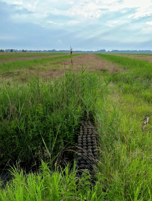
Constructed wetlands need substantially more land than mechanical plants with equivalent hydraulic capacity — a CW footprint can run an order of magnitude (roughly 5–20×) larger than a comparable MBR or activated sludge system, depending on target loading and effluent quality (S4, ScienceDirect). This footprint requirement can rule out a standalone CW for space-constrained industrial sites and force a hybrid approach.
Clogging is the dominant failure mode. It arises from inadequate upstream pretreatment, excessive hydraulic loading, or unsuitable substrate selection and configuration (De Matos et al., 2018, as cited in S4). Once the media voids fill with biomass and accumulated solids, the bed short-circuits, hydraulic retention time collapses, and removal efficiency drops. The fix is rarely retrofitting more wetland — it is fixing the headworks, the DAF, or the chemical precipitation step upstream.
Three other failure modes deserve equal weight in a 2026 design review. First, cold-climate performance loss: subsurface flow CWs in particular suffer sharp BOD/COD and ammonia removal drops in winter (Fan et al. and Leto et al., as cited in S4). Second, greenhouse gas emissions: CWs can release methane and nitrous oxide, and bio-electrochemical integration is one of the few mitigation routes showing measurable control (S4, ScienceDirect). Third, plant selection risk: an incorrectly chosen aquatic plant will underperform, which is why plant species is treated as a critical design variable rather than an aesthetic choice (S4, ScienceDirect). Industrial chemistry limits are equally binding — CWs will not handle high-strength toxicants, oil and grease, or hydraulic shock loads without robust upstream pretreatment.
CW Configurations Compared: FWS, VF, HF, and Hybrid
Configuration drives performance more than any other design choice. The table below summarizes typical hydraulic retention time (HRT), target pollutant, footprint, and best industrial application across the four main variants, plus two emerging hybrids documented in the 2024 research record (S4, ScienceDirect).
| Configuration | Typical HRT | Best at removing | Footprint | Best application |
|---|---|---|---|---|
| Free Water Surface (FWS) | 5–14 days | BOD, TSS, ammonia | Largest | Municipal polishing, landfill leachate, large rural sites with mosquito/odor tolerance |
| Vertical Flow (VF) | 1–3 days (intermittent dosing) | Ammonia (nitrification), BOD | Medium | Tertiary nitrification step; needs dosing control and resting cycles |
| Horizontal Flow (HF) | 3–10 days | Nitrate (denitrification), metals, organics | Medium | Industrial polishing for nitrate and metals; risk of surface clogging |
| Hybrid VF + HF in series | 4–12 days combined | Ammonia + nitrate (full N train), BOD | Medium-large | Strongest single-train polishing for ammonia + nitrate; common in EU and UK designs |
| e-PCW (microelectrolysis + pyrite filler) | 2–5 days | Phosphorus, refractory organics | Medium | Eutrophic water and polishing of refractory COD |
| Eisenia fetida earthworm-integrated CW | 3–7 days | Microplastics, organic pollutants | Medium | Microplastic and ARG polishing downstream of biological treatment |
For most industrial buyers, the realistic configuration decision is between an HF cell (for metal and nitrate polishing) and a hybrid VF+HF train (when ammonia is the binding effluent limit). The emerging e-PCW and earthworm-integrated variants are still research-stage for most sites, but they are documented enough to mention in a 2026 pilot scope.
Where CWs Fit in an Industrial Treatment Train
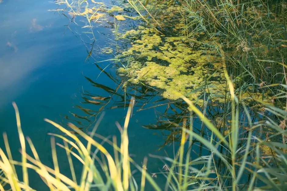
CWs belong downstream of mechanical screening, primary clarification or dissolved air flotation, and a biological step — never as the sole barrier for high-strength industrial streams. A defensible 2026 train for, say, a food processing or landfill leachate site is: a rotary mechanical bar screen for headworks protection, a DAF system for oil, grease, and TSS removal, an MBR membrane bioreactor as the upstream biological step, and a horizontal flow or hybrid VF+HF CW as the polishing wetland. Automatic chemical dosing for pH and metal precipitation sits between the DAF and the MBR, especially on electroplating and metal-finishing lines.
This integration pattern is more than theory. An integrated CW has been shown to improve WWTP effluent quality before release into a chalk stream, with measurable reduction in antibiotic resistance genes (ARGs) and microplastics (S4, ScienceDirect). Electroplating and landfill leachate are the two industrial niches with the strongest published track record, including the Saint-Étienne/Silesian work on metals and cyanide (S1) and the CWA database entries for landfill leachate sites (S3, Springer).
The list of where not to specify a CW is equally important. Skip a standalone CW when influent COD is consistently above ~1,500 mg/L, when ammonia peaks exceed design assumptions, when the available footprint drops below roughly 0.5 m² per m³/d of flow, when the climate stays sub-zero for long winter periods and there is no heating or insulation budget, or when the discharge permit demands sub-10 mg/L effluent nitrogen on multiple parameters. For more on selecting between treatment stages, see the secondary vs tertiary treatment comparison, and for compliance scoping on chemical and metal-bearing streams, the chemical wastewater reuse compliance in 2026 guide. The specific industrial reference for the electroplating case is the electroplating effluent treatment process walkthrough.
Decision Framework: When a Constructed Wetland Is (and Isn't) the Right Choice in 2026
Use the matrix below as a project-review filter before committing to a CW scope. Cost framing is qualitative because the research record does not converge on a single dollar figure: a standalone CW has lower OPEX and higher land CAPEX, while an MBR has higher OPEX and lower land CAPEX (S4, ScienceDirect).
| Project condition | Choose standalone CW | Hybridize CW + MBR/DAF | Avoid CW; use MBR or activated sludge |
|---|---|---|---|
| Land available, affordable | Yes | Yes | No |
| Influent COD > 1,500 mg/L | No | Only with strong upstream biological step | Yes |
| Footprint < ~0.5 m² per m³/d | No | No | Yes |
| Sub-zero winters, no heating budget | No | Insulate or cover; otherwise avoid | Yes |
| Permit demands < 10 mg/L N on multiple parameters | No (hybrid only) | Yes — hybrid VF+HF polishing | Only if hybrid cannot meet limit |
| Sustainability / EOC removal is a stated KPI | Yes (CW is the differentiator) | Yes (CW tail polish) | EOC removal is weaker without CW |
| Operating skill is limited on site | Yes | Yes (CW is the low-skill stage) | MBR membrane care requires more training |
The technology is no longer experimental, given the 1,200+ CW systems installed in the UK tracking sewage, mine water, landfill leachate, industrial effluents, surface run-off, and road run-off (S3, Springer). For a 2026 industrial buyer, the question is not "does a CW work" but "is the influent, the land, the climate, and the permit aligned with a CW's actual operating envelope" — and if not, where the hybrid boundary should sit.
Frequently Asked Questions
What is the main disadvantage of constructed wetlands?
Land footprint is the binding disadvantage: a constructed wetland typically needs 5–20× the area of an equivalent MBR or activated sludge plant for the same flow, and it is vulnerable to clogging, cold-climate performance loss, and methane/nitrous oxide emissions (per ScienceDirect, 2024).
Are constructed wetlands effective for industrial wastewater?
Yes, as a tertiary polishing step. A 2013 Saint-Étienne/Silesian thesis documented the first metal and cyanide removal from electroplating wastewater in subsurface flow constructed wetlands, and the UK CWA database includes industrial effluent, landfill leachate, and mine water sites (per theses.fr, 2013, and Springer, 2008).
What is the difference between FWS, VF, and HF constructed wetlands?
Free water surface (FWS) wetlands hold exposed water and target BOD/TSS/ammonia. Vertical flow (VF) wetlands are dosed intermittently and drive nitrification. Horizontal flow (HF) wetlands run saturated and target denitrification and metal removal. A hybrid VF+HF train combines both for ammonia + nitrate polishing (per ScienceDirect, 2024).
How much do constructed wetlands cost compared to MBR?
No single canonical dollar figure exists in the peer-reviewed record. Qualitatively, a standalone CW has lower OPEX and higher land CAPEX, while an MBR has higher OPEX (energy, membrane replacement) and lower land CAPEX