Why the Pretreatment Frame Stacks in Three Layers for Hackensack-Area Fabs
Hackensack-area semiconductor fabs operate under a three-layer regulatory stack in which the lowest layer is a floor, not a ceiling: the EPA Industrial Pretreatment Program at 40 CFR Part 403 establishes the "industrial user" duty to control pass-through, interference, and sludge contamination; 40 CFR Part 413 layers on the semiconductor-specific categorical effluent limits; and the receiving NJ POTW's Sewer Use Ordinance sits on top, almost always as the strictest ceiling (per EPA 40 CFR 403/413). For a Bergen County fab the receiving POTW is typically the Passaic Valley Sewerage Commissioners (PVSC) — Newark — or the Bergen County Utilities Authority (BCUA), each with its own published local limits, slug-control plan, and IPP permit cycle. A 2023 openRxiv assessment of US sewer connectivity found downstream POTW capacity is highly uneven across the country, which means a fab clearing the 40 CFR 413 floor can still fail a small-POTW local limit — Hackensack is not a "small POTW" case, but the principle is the same: read the SUO and the most-recent IPP discharge permit line by line before any equipment is sized, and before the first CaCl2 dose rate is set (openRxiv 2023-05).
EPA's pretreatment program guidance (epa.gov) makes this explicit: local limits are site-specific, can be numeric or narrative, and a POTW may impose them tighter than the categorical floor when headworks, digesters, or receiving waters require it (per EPA 40 CFR 403.5(c)). New Jersey adds a state overlay — N.J.A.C. 7:14A — that the PVSC SUO and BCUA permit both rest on, with fluoride and trace-metal ceilings that track federal floors but are rarely identical. Engineers who design to the categorical ceiling and back-fit SUO paperwork keep plants out of Significant Non-Compliance (SNC); engineers who design to the categorical floor and hope the local limit is permissive do not.
| Regulatory layer | What it sets | Binding behavior at a Hackensack-area fab |
|---|---|---|
| 40 CFR Part 403 (IPP) | General duty: no pass-through, no interference, no sludge contamination | Program framework; rarely a numeric ceiling by itself |
| 40 CFR Part 413 (semiconductor categorical) | Daily and monthly maxima for fluoride, metals, TSS, O&G | Categorical floor; rarely the binding ceiling in NJ |
| PVSC / BCUA Sewer Use Ordinance (N.J.A.C. 7:14A overlay) | Site-specific pollutant ceilings, monitoring frequency, slug-control plan, IPP permit term | Almost always the strictest of the three; design to this |
The practical instruction is unglamorous but decisive: pull the receiving POTW's SUO, the most-recent IPP discharge permit, and any N.J.A.C. 7:14A appendices before sizing a PLC-controlled automatic chemical dosing skid with pH and fluoride ISE feedback. The local document is the only one a PVSC inspector will cite when an SNC finding lands.
The Pollutants That Actually Drive Fab Pretreatment Design Near Hackensack
Four pollutant families drive pretreatment design at a Hackensack-area fab, and each one forces a different unit operation onto the P&ID. Wet-etch and cleaning drains carry HF and NH4F at 50–500 mg/L as fluoride plus strong and weak acids — almost always the binding stream because fluoride is the parameter the receiving POTW regulates most tightly. CMP slurry and filter backwash contribute suspended fine oxide particles and dissolved Cu, Ni, Co, Cr, Pb, and Ag, typically enforced at ≤1–3 mg/L individual and ≤5 mg/L combined in NJ-area SUOs. Developer drains carry TMAH at 100–200 mg/L where the POTW accepts it; TMAH biodegrades to ammonia and pushes the NH3-N ceiling to roughly 50 mg/L, which means the developer stream has to be handled on its own pH/temperature schedule regardless of how convenient it would be to combine it with the rest of the fab drain. Utility-floor drains contribute lubricants, oil, lint, and hair — the reason a coarse screen earns its place at the head of the train (O&G ≤10–50 mg/L, TSS ≤30–60 mg/L).
Fluoride is the single parameter that most often forces a dedicated treatment stage. HF and NH4F from wet-etch and post-etch cleaning routinely enter fab wastewater at 50–500 mg/L, well above the 10–25 mg/L ceiling common in US POTW ordinances. The categorical fluoride limit is set far below the toxicity threshold for POTW biomass because fluoride at 20–30 mg/L already inhibits methanogenic activity in downstream anaerobic digesters — the same phenomenon covered in more detail in any anaerobic digester engineering guide. Removing fluoride to single-digit mg/L requires a dedicated calcium-driven precipitation step that the rest of the train is then designed around. Three engineering consequences fall out of this parameter map: no single unit operation can hit all four ceilings (segregation is mandatory); the fluoride ceiling is the only one tight enough to force a dedicated chemical-precipitation stage; and the TMAH → NH3-N linkage means the developer stream cannot share a header with the metal-bearing CMP stream.
| Stream family | Source | Key parameters | Typical NJ-area ceiling |
|---|---|---|---|
| Wet-etch / cleaning | HF, NH4F baths; post-etch rinses | Fluoride 50–500 mg/L influent; strong/weak acids | 10–25 mg/L F (POTW-specific) |
| CMP / plating / BEOL | Slurry waste, filter backwash, metallization | Cu, Ni, Co, Cr, Pb, Ag dissolved; fine oxide TSS | ≤1–3 mg/L individual; ≤5 mg/L combined |
| Photoresist developer | TMAH-bearing drains; wafer cleaning | TMAH; biodegrades to NH3-N | TMAH 100–200 mg/L (POTW-dependent); NH3-N ~50 mg/L |
| Utility floor drains | Tool lubricants, pump seal leaks, lint, hair | O&G; TSS; particulates | O&G ≤10–50 mg/L; TSS ≤30–60 mg/L |
Two Hackensack-area specifics are worth pinning to the wall before equipment selection starts. First, the PVSC service area sits in the Passaic Basin, which the New Jersey Department of Environmental Protection classifies as water-stressed — a fact that pushes fabs toward reuse targets and therefore toward the polishing stage, not just the compliance floor. Second, BCUA's SUO and PVSC's SUO do not present identical parameter lists; a fab discharging to one versus the other will size different chemical tanks, different ISE calibration schedules, and different slug-control basins. The receiving POTW's name belongs on the cover sheet of the pretreatment basis-of-design report, not buried in an appendix.
The Four-Stage Hackensack Pretreatment Train: P&ID Order and Why It Cannot Be Reordered
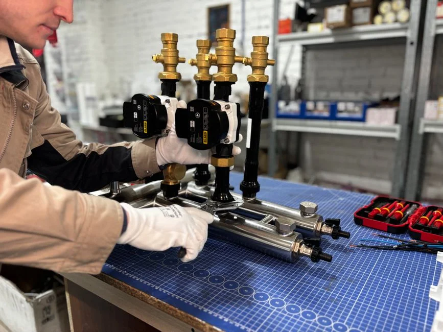
A properly designed fab pretreatment train is a four-stage sequence drawn on the P&ID in the order shown below. Each stage is sized against the design-day pollutant mass load (kg/day), not the average flow, because batch discharges from wet-etch tools and post-CMP cleaning can swing the instantaneous fluoride load by a factor of 3–5× over the daily average (HydropureWater field data, 2026). Reordering the stages forces a compromise chemistry somewhere in the train, and the compromise always lands on the parameter with the tightest ceiling — which in NJ is fluoride.
Stage 1 — Source Segregation. Fluoride-bearing streams from wet-etch and post-etch cleaning are kept separate from CMP slurry waste and from TMAH/ammonia developer streams. The reason is pH: fluoride precipitates efficiently only in the 6–8 range, metal-hydroxide precipitation from CMP waste works best at 9–10.5, and TMAH biodegradation is fastest outside the fluoride window. Combining them forces the operator to dose toward a compromise pH and accept higher reagent consumption. Segregation is a piping decision made at fab design time and is almost impossible to retrofit cheaply — flag it as a critical early-stage scope item on any new build and as a major capex line on any brownfield upgrade.
Stage 2 — pH Neutralization and Chemical Precipitation. Calcium chloride (CaCl2) — or lime, Ca(OH)2 — is dosed into the fluoride stream to drive precipitation of CaF2 (Ksp ≈ 3.9 × 10⁻¹¹), which confirms calcium-driven precipitation is thermodynamically capable of single-digit mg/L effluent at the right pH. Sodium hydroxide or lime is then dosed into the metal-bearing stream to drive metal hydroxides. Dose control is the heart of the system: a PLC-controlled automatic chemical dosing skid with pH and fluoride ISE feedback typically holds reagent addition within ±5% of setpoint, which is the difference between meeting a 15 mg/L fluoride cap and exceeding it. The two streams are then recombined into a single equalization basin ahead of solids separation. Long-term pH-probe reliability is a known failure mode on this stage — redundant pH probes and an auto two-point calibration routine on the fluoride ISE are the standard fix.
Stage 3 — Solids/Liquid Separation. The precipitated CaF2 and metal-hydroxide floc are removed in either a DAF system for Stage 3 solids separation or a high-efficiency lamella clarifier at 20–40 m/h surface loading. DAF is preferred for high-flow, low-density, or oily streams at 4–25 m/h hydraulic loading; lamella is preferred where footprint is constrained and the solids are denser at 20–40 m/h. Both routinely deliver overflow TSS below the 30–60 mg/L SUO range when the upstream chemistry is correct.
Stage 4 — Polishing. An industrial RO polishing system at 75–95% recovery per pass or ion-exchange resin beds polish the effluent to single-digit µg/L on most parameters and bring TDS and residual fluoride down to levels suitable for non-critical rinsing, cooling-tower makeup, or scrubber feed. RO permeate that is not reused is sewered well below any applicable limit. For chromium-bearing streams — increasingly common in third-generation semiconductor work — a dedicated Cr(VI) reduction and precipitation step is required upstream of the rest of the train; flag it as a scope item, not a footnote.
| Stage | Function | Operating window | Output spec |
|---|---|---|---|
| 1 — Source segregation | Split fluoride, metals, TMAH onto separate headers | Decided at fab design | Three pH-compatible streams |
| 2 — pH neutralization & precipitation | CaCl2/lime dose; NaOH/lime dose; PLC + ISE feedback | pH 6–8 (F); pH 9–10.5 (metals); ±5% dose control | Single-digit mg/L F; metals at solubility limits |
| 3 — Solids/liquid separation | DAF or lamella clarification | DAF 4–25 m/h; lamella 20–40 m/h | Overflow TSS ≤30–60 mg/L |
| 4 — Polishing | Ion exchange and/or RO | RO 75–95% recovery/pass; IX ≤50 m³/h typical | Single-digit µg/L metals; reuse-grade TDS |
The order is not negotiable. Fluoride has to be precipitated before metals (its Ksp demands it), and solids have to be removed before the polishing membranes (fouling economics demand it). The Hackensack-area overlay that complicates an otherwise textbook train is the discharge temperature window: BCUA and PVSC both enforce a maximum discharge temperature in the SUO, and a CaF2 precipitate that drops out of a hot equalization basin behaves differently from one that drops out of a cooled basin. Engineer the equalization tank with mixing and residence time for the actual discharge temperature, not for a textbook 25 °C.
Equipment Selection Matrix: Translating the Train into a Hackensack-Ready BOM
Translating the four-stage narrative into procurement-ready equipment comes down to five selection decisions an EPC or process engineer actually makes on a Hackensack-area fab. A coarse screen at the head of the train protects everything downstream and is one of the highest-ROI line items on the entire BOM. A GX-series rotary mechanical bar screen at the head of the train with 2–6 mm bar spacing and auto-cleaning, sized to the design-day peak flow, prevents particulates, hair, and lint from utility-floor drains from damaging dosing-pump diaphragms and clogging the DAF recycle eductor. Low CapEx, very high OpEx-protection ROI.
For Stage 2, the PLC-controlled automatic chemical dosing skid with pH and fluoride ISE feedback is sized on peak fluoride and metal mass load (kg/day), not average flow. Specify a turndown ratio of at least 10:1 on the metering pumps, require the skid to accept both 4–20 mA flow-pacing and pH/ISE feedback, and confirm it includes redundant pH probes plus a fluoride ISE with automatic two-point calibration. This is the difference between a system that tracks the load and one that overdoses caustic during a rinse-water spike.
For Stage 3, the DAF-versus-lamella decision is driven by three numbers: peak flow (m³/h), influent TSS after coagulation, and footprint. A DAF system for Stage 3 solids separation handles 4–300 m³/h with float scraping and is the right answer for fluoride-rich or oily streams with high float loading. A high-efficiency lamella clarifier at 20–40 m/h surface loading wins when flows are moderate, solids are denser, and the building bay is tight. For a deeper P&ID walk-through, see the DAF system process flow diagram 2026 engineering walkthrough.
For Stage 4, the industrial RO polishing system at 75–95% recovery per pass is selected when the fab has a documented reuse target (≥50% recycle of the pretreatment effluent) and an industrial-grade reject-stream management plan. Ion exchange is selected when the polishing duty is primarily trace metals and hardness, throughput is ≤50 m³/h, and the operator is comfortable with resin regeneration cycles. For the upstream fluoride chemistry that feeds Stage 4, the HF wastewater treatment by calcium fluoride precipitation engineering guide is the relevant cross-reference.
| Stage | Selection criterion | Recommended spec band | Cost framing |
|---|---|---|---|
| Head-of-train screening | Bar spacing; design-day peak flow; auto-cleaning | 2–6 mm bar spacing | Low CapEx; very high OpEx-protection ROI |
| Stage 2 dosing skid | Peak fluoride + metal load (kg/day); turndown; feedback | 10:1 turndown; 4–20 mA + pH/ISE feedback | Moderate CapEx; dominates OpEx via reagent use |
| Stage 3 separation | Peak flow; TSS; footprint | DAF 4–300 m³/h; lamella 20–40 m/h SLR | DAF higher CapEx; lamella higher CoDense footprint penalty |
| Stage 4 polishing | Reuse target; throughput; regeneration tolerance | RO 75–95% recovery; IX single-digit µg/L | RO high CapEx/OpEx; IX moderate CapEx, resin OpEx |
One Hackensack-area line item that the top-ranking generic tutorials do not call out: a temperature trim cooler on the equalization basin effluent ahead of the DAF. PVSC and BCUA both enforce a maximum discharge temperature in the SUO, and a CaF2 precipitate that drops out of a 40 °C basin settles differently from one that drops out of a 25 °C basin — both for crystal size and for the residual fluoride that stays in solution. Add it to the BOM.
Online Monitoring, DMRs, and the 5-Year IPP Permit Cycle in New Jersey
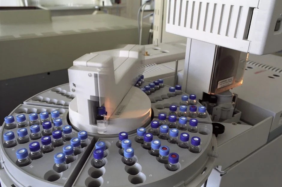
Equipment alone does not keep a fab in compliance; the online instrument suite does. The minimum IPP monitoring package for a fab regulated under 40 CFR 403 is a pH probe and a fluoride ion-selective electrode (ISE) on the combined effluent header, plus a total-metals analyzer — typically an on-line ICP-OES or XRF-on-line unit — for Cu, Ni, Cr, and any other metal the SUO specifically lists. Continuous monitoring satisfies the 24/7 expectation most NJ POTWs now write into IPP permits and gives the operations team minutes of warning before a limit is exceeded, not hours. ISE calibration on a two-point auto-cal routine is the single most common SOP gap that surfaces in NJ POTW inspections — write the calibration interval into the SOP, not into a tribal-knowledge spreadsheet.
The operational frame that turns equipment into a compliance program is the IPP permit cycle. A new or re-issued IPP permit in NJ runs 5 years and binds the fab to monthly Discharge Monitoring Reports (DMRs), routine POTW inspections (annual baseline, more frequent for Significant Non-Compliance facilities), and a slug-control plan for accidental releases. Every piece of equipment on the train must be backed by an SOP and a calibration record, because the POTW inspects both the hardware and the paperwork. N.J.A.C. 7:14A adds the state-level reporting overlay on top of the federal DMR cadence; missing the NJ-specific reporting format is one of the most common SNC findings at first-time-discharge fabs in Bergen County.
Hackensack-Localized Overlay: Sludge, TCLP, and the Haul-vs-Sewer Cost Math
The solids removed in Stage 3 — CaF2, metal hydroxides, and CMP residue — report as a thickened sludge typically at 1–4% dry solids. A plate and frame filter press for 25–35% dry-solids cake, sized from 1 m² (pilot) to 500 m² (full fab, multi-press line), dewaters that sludge to a 25–35% dry-solids cake for off-site disposal. Filtrate returns to the head of the train and is not lost to the mass balance. Disposal routing is the cost swing on the back end: if the upstream chemistry produces a sludge that retains pollutants through EPA's Toxic Characteristic Leaching Procedure (TCLP), the cake can be disposed of as non-hazardous waste in a municipal landfill at a fraction of the hazardous-waste disposal rate. Polymer flocs often fail TCLP and re-leach under dewatering pressure; one-step bentonite-based separating chemistries are engineered to retain pollutants through TCLP (per siliconsemiconductor.net, 2025-09).
The Hackensack-area cost framing is sharper than the generic tutorials allow. Sewer discharge is the cheap path, and it is the only path that scales with fab throughput. Hauling liquid hazardous waste off-site runs roughly 5–10× the cost per cubic meter of sewer discharge (per industry benchmarks, 2025-09). For a Bergen County fab, where hazardous-waste hauling distances to a permitted TSDF already run 40–80 miles one way, the multiplier sits at the higher end of that range, which is exactly the math that makes pretreatment CapEx pay back the moment the haul-vs-sewer crossover is crossed. The engineer who specifies a robust Stage 2 chemistry also closes the loop on Stage 3 solids handling — these are not separable decisions, and a procurement committee that tries to optimize them independently will overpay on one side and under-comply on the other. For a comparable compliance frame on a different feedstock, see the inorganic chemicals plants near Houston pretreatment compliance guide and the how NGL and petroleum refineries near Houston meet pretreatment limits piece.
Frequently Asked Questions
What are the binding discharge limits for a semiconductor fab discharging to PVSC?
A fab discharging to PVSC operates under a three-layer ceiling: 40 CFR Part 403 (general IPP duty), 40 CFR Part 413 (semiconductor categorical), and the PVSC Sewer Use Ordinance, which is almost always the strictest. Typical PVSC ceilings run 10–25 mg/L fluoride, ≤1–3 mg/L individual heavy metals, ≤5 mg/L combined metals, ≤30–60 mg/L TSS, and NH3-N around 50 mg/L. Pull the current PVSC SUO and IPP permit before sizing any equipment.
How is fluoride removed to single-digit mg/L before sewer discharge in a fab?
Calcium chloride or lime is dosed into the fluoride-bearing stream to precipitate calcium fluoride (CaF2) with a Ksp of approximately 3.9 × 10⁻¹¹, operating in the pH 6–8 window. A PLC-controlled dosing skid with a fluoride ion-selective electrode holds the reagent dose within ±5% of setpoint and delivers single-digit mg/L fluoride on a well-tuned system, with the precipitated solids removed downstream by DAF or lamella clarification.
What online monitoring does a Hackensack-area fab need to stay out of Significant Non-Compliance?
At minimum: a pH probe and a fluoride ISE on the combined effluent header, plus an on-line ICP-OES or XRF-on-line unit for Cu, Ni, Cr, and any metal specifically listed in the receiving POTW's SUO. Continuous monitoring satisfies the 24/7 expectation most NJ POTWs now write into IPP permits, gives the operations team minutes of warning instead of hours, and feeds the monthly Discharge Monitoring Reports required under the 5-year IPP permit cycle.
Why is source segregation done at the piping level instead of as a packaged unit?
Because fluoride precipitates at pH 6–8, metal hydroxides at pH 9–10.5, and TMAH biodegrades fastest outside the fluoride window, combining the three streams forces the operator to dose toward a compromise pH and accept higher reagent consumption. Segregation is a piping decision made at fab design time and is almost impossible to retrofit cheaply — it has to be locked in before the wet-etch and CMP tool headers are pinned out, not after startup.
What does it cost a Bergen County fab to skip pretreatment and haul liquid waste instead?
Off-site hauling of liquid hazardous waste runs roughly 5–10× the cost per cubic meter of sewer discharge (per industry benchmarks, 2025-09), and the multiplier sits at the higher end in Bergen County because permitted TSDFs are 40–80 miles one way. Pretreatment CapEx typically pays back the moment the haul-vs-sewer crossover is crossed, which for most fab-scale flows happens within the first year of operation.