Why Houston NGL and Refinery Pretreatment Compliance Is Getting Harder in 2026
A mid-sized refinery along the Houston Ship Channel gets a Notice of Violation in early 2026 from a local POTW for oil and grease at 187 mg/L and total sulfide at 4.2 mg/L on a desalter effluent composite sample, after a six-week period of crude slate changes pushed emulsified oil past the API/DAF train's normal envelope. The federal rule on the book — 40 CFR Part 419 — was last amended in 1985, but the local Houston-area POTW's oil and grease, sulfide, and ammonia limits have tightened repeatedly over the last decade and now set the binding design target. That is the operating reality in 2026: the compliance stack is two-layered, and the local limit is almost always the limit that matters.
The Houston Ship Channel is the largest petrochemical complex in the United States, hosting a dense cluster of NGL fractionators and refineries whose wastewater ultimately discharges to the City of Houston's wastewater system or to a tributary industrial authority. Expanding NGL fractionation capacity tied to Permian and Eagle Ford gas production has added new wastestreams (amine still bottoms, glycol regeneration waste, produced water) into a sewer network that was historically designed for refinery process water alone. Pretreatment programs in the region have responded by tightening local limits, increasing self-monitoring requirements, and elevating enforcement on slug-load events.
Designing a 2026-compliant pretreatment train therefore requires three things in parallel: a defensible reading of the federal rule (40 CFR Part 419), an accurate reading of the local POTW's local limits, and an engineering train — API oil–water separator, DAF system for refinery wastewater pretreatment, equalization, biological treatment, polishing, and disinfection — that demonstrably hits the binding target for every regulated wastestream. This article walks each layer in turn, with the unit-process parameter targets a 2026 design must hit.
The Regulatory Stack: 40 CFR Part 419, RCRA Subtitle D, and the Houston POTW Pretreatment Program
40 CFR Part 419, the Petroleum Refining Effluent Guidelines and Standards, is the federal rule covering wastewater discharges at more than 140 U.S. refineries; EPA promulgated it in 1974 and last amended it in 1985 (per the EPA Effluent Guidelines page). The rule is incorporated into NPDES permits for direct dischargers and into pretreatment program controls for indirect dischargers — the latter being the path most Houston Ship Channel plants use because they send wastewater to a municipal or industrial POTW rather than discharging directly to surface water.
40 CFR Part 419 organizes covered refineries into four subcategories based on process configuration, and the applicable limits depend on which subcategory applies to a given plant:
| Subcategory | Process Configuration | Applicability to Houston Area |
|---|---|---|
| 1 | Topping only (separating crude; may include desalting, atmospheric/vacuum distillation, asphalt, lube) | Limited; few stand-alone topping plants on the Ship Channel |
| 2 | Topping + catalytic cracking + petrochemical | Common at integrated refining/petrochemical sites |
| 3 | Topping + cracking + lube oil manufacturing | Found at facilities with lube or base-oil production |
| 4 | Topping + cracking + lube + petrochemical | Applies to fully integrated complexes |
Refinery operators should select the subcategory by walking through their unit operations, not by NAICS code alone — the EPA Effluent Guidelines page explicitly notes that the NAICS group listing is a guide and that precise coverage is defined in 40 CFR Part 419 applicability sections.
E&P-type wastes — flowback, drill cuttings, and certain produced-water streams generated at NGL receipt stations and gas plants — fall under RCRA Subtitle D (40 CFR Part 257) as solid waste, not under 40 CFR Part 419 (per the EPA oil and gas exploration and production waste page). These streams often cannot be sewered at all and may require Class II injection-well disposal, on-site treatment, or specialized handling. Where an NGL plant is co-located with a refinery, the segregation point between "process wastewater" (Part 419) and "E&P waste" (Subtitle D) is a frequent audit finding and worth resolving in writing with the local POTW before any rerouting.
Houston-area pretreatment is enforced by the City of Houston's Industrial Wastewater Program and by tributary industrial authorities, each of which sets local limits typically more stringent than the federal floor. Common 2026 local limit ranges reported in regional discharge permits include oil and grease at or near 100 mg/L, total sulfide 1–10 mg/L, ammonia 10–50 mg/L, pH 6–9, and tight daily-maximum ceilings for phenols, chromium, and benzene. Because the local limit is binding, the design target should be the local limit minus an operating safety margin, not the federal 40 CFR Part 419 value.
Refinery and NGL Wastestreams: What Goes Into the Pretreatment Train
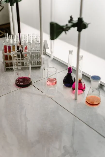
Per the EPA Effluent Guidelines page, the wastestreams covered by 40 CFR Part 419 at a conventional refinery include desalter effluent, process wastewater from steam stripping and fractionating, sour water stripper overhead, spent caustic, once-through cooling water, cooling-tower blowdown, boiler blowdown, ion-exchange or RO reject water, contaminated and uncontaminated stormwater, and ballast water. Each stream has a different characteristic profile and arrives at the WWTP headworks on a different schedule, which is why segregation and equalization matter as much as the unit processes downstream.
| Wastestream | Key Pollutants | Typical Handling |
|---|---|---|
| Desalter effluent | Oil & grease, TSS, TDS, chlorides | Segregated; routed to API + DAF |
| Sour water stripper feed/overhead | H2S, NH3, phenols | Stripped upstream; overhead condensate to biotreatment |
| Spent caustic | High pH, sulfides, phenols | Neutralized; often sent to wet oxidation or sidestream |
| Cooling-tower blowdown | TDS, chromate residuals (legacy), biocides | May go to blowdown treatment before sewer |
| Boiler blowdown | TDS, hydrazine (legacy), iron | Cooling, then to equalization |
| Stormwater (contaminated) | Oil, TSS, PAHs | Routed through API + DAF |
| Ballast water | Oil, TDS | Routed to API separator |
| Amine still bottoms (NGL) | H2S, CO2, amine, heat-stable salts | Dedicated sidestream stripper before biotreatment |
| Glycol regeneration waste (NGL) | High BOD/COD, glycols, TEG/DEG | Equalization and biological; high BOD load |
| Produced water (NGL receipt) | TDS, chlorides, trace hydrocarbons, heavy metals | Often Class II disposal; only sewered with POTW approval |
NGL fractionation plants add streams that a conventional refinery does not see at the same intensity: amine still bottoms rich in H2S and CO2 from gas sweetening, glycol regeneration waste with high BOD/COD from dehydration units, hydrocarbon skimmings from slug-catchers, and produced water from receipt stations (HydropureWater field data, 2026). When co-located with a refinery, these streams are typically routed to the refinery WWTP — but only after segregation and a dedicated sour-water stripper pass for the amine bottoms. Bottom sediment and water (BS&W) from crude storage is a separate sludge stream and does not flow through the sewer; it is handled in sludge processing.
Segregation is the single most underestimated design variable. Desalter brine, sour water, and spent caustic each have characteristics (TDS up to 100,000 mg/L, sulfide in the hundreds of mg/L, pH >12) that would damage biological treatment if blended raw. Treating them as sidestreams, then blending the sidestream effluents into the main equalization basin, protects the downstream biotreatment stage from shock loads and keeps the 2026 effluent profile in range.
Pretreatment Unit Processes: From the API Separator to Disinfected Discharge
The standard refinery pretreatment train is a five-stage sequence: API oil–water separator → DAF → equalization → biological treatment → polishing/disinfection. Each stage targets a specific pollutant class, and the design parameter ranges below are the 2026 envelope a Houston engineer should be working against.
| Unit Process | Design Parameter / Range | Typical Removal / Effluent |
|---|---|---|
| API oil–water separator | 1.5–2 hr residence time; API design standard 4215 basis; grit/sand removal upstream | 60–95% free oil removal; cannot remove emulsified oil or fine TSS |
| Dissolved air flotation (DAF) | 10–30% recycle ratio; hydraulic loading 5–25 m³/m²·hr; automatic chemical dosing for DAF and pH adjustment for coagulant/flocculant | 50–90% oil & grease removal; effluent oil & grease 50–100 mg/L post-API+DAF |
| Equalization | 8–24 hr HRT at Houston refineries; mixing and aeration | pH and slug-load dampening; stabilizes feed to biotreatment |
| Biological treatment (CAS / SBR / MBR) | MLSS 3,000–5,000 mg/L (CAS); HRT 6–24 hr; SRT 10–30 days for nitrification; MBR system for refinery and NGL wastewater delivers <5 mg/L TSS | BOD <30 mg/L, COD >70% removal, ammonia <10–20 mg/L, TN removal with denitrification |
| Polishing & disinfection | Multimedia filtration (sand/anthracite) and/or activated carbon; ClO2 disinfection for refinery final effluent at 0.5–2 mg/L residual | TSS <30 mg/L; residual organics and microbiological counts reduced for sewer discharge |
| Sidestream treatment | Sour water stripper; spent caustic neutralization; DAF sludge dewatering | Sidestreams 5–25% of main plant load; treated before return |
After API + DAF, oil and grease is typically below 50–100 mg/L — sufficient to meet most Houston POTW local limits on that single parameter, but not sufficient to meet the tighter ammonia, sulfide, and BOD limits that drive biotreatment design (HydropureWater field data, 2026). Equalization at 8–24 hr HRT dampens the slug loads that an NGL receipt station or a crude-slate change can send into the WWTP. The biological stage is where the 2026 design earns its keep: conventional activated sludge (CAS) with nitrification/denitrification is the workhorse, but MBR variants are increasingly specified because they hold <5 mg/L TSS, recover quickly from upsets, and reach ammonia targets that CAS struggles to sustain at low temperatures or high TDS.
Polishing — multimedia filtration followed by activated carbon — strips residual COD and phenols, and disinfection is the final barrier before the sewer. Houston's 2026 standards favor chlorine dioxide (ClO2) over chlorination because ClO2 forms fewer regulated DBPs and is approved under EPA drinking-water programs for the contact-time range a refinery needs. The realistic 2026 effluent profile a Houston engineer should target across the train: oil & grease <50 mg/L, TSS <30 mg/L, BOD <30 mg/L, sulfide <1 mg/L, pH 6–9, ammonia <10–20 mg/L (HydropureWater field data, 2026).
How NGL Fractionation Plants Adapt the Same Train
NGL fractionation plants share the same five-stage skeleton as a refinery, but the loading profile is different. Hydrocarbon throughput per barrel of wastewater is lower, while specific loading of H2S, CO2, amine, and glycol is higher because gas-sweetening (amine contactors), dehydration (TEG/DEG units), and produced-water handling concentrate these constituents into a smaller wastewater volume (typically 10–500 m³/day for a stand-alone NGL plant, per HydropureWater project data 2026).
The most important regulatory distinction: E&P-type waste streams at NGL receipt stations — flowback, certain produced water, and tank bottoms — fall under RCRA Subtitle D (40 CFR Part 257) for solid-waste management, not under 40 CFR Part 419 (per the EPA oil and gas exploration and production waste page). These streams often cannot be sewered without specific POTW or state approval and may require Class II injection-well disposal. The default design assumption is that produced water and tank bottoms are not sewered; only process wastewater from the fractionation train itself, after segregation, enters the refinery WWTP or the stand-alone pretreatment train.
For NGL plants co-located with a refinery, the recommended routing is: amine still bottoms → dedicated sour-water stripper → condensate to refinery WWTP; glycol regeneration waste → equalization → biological (segregate from amine bottoms because of pH and load differences); produced water → produced-water treatment or Class II disposal, not the sewer. For stand-alone NGL plants, a small-footprint DAF + SBR or DAF + MBR skid is the typical 2026 answer — factory-tested units reduce on-site construction time and can be sized to the 10–500 m³/day flow range without overbuilding.
2026 Compliance Checklist for Houston-Area NGL and Refining Plants
The following five-step checklist is what a process or environmental engineer should be able to walk into a 2026 audit with:
| Step | Action | Output |
|---|---|---|
| 1 | Map every wastestream to either 40 CFR Part 419 or RCRA Subtitle D (40 CFR Part 257), confirming with the EPA Effluent Guidelines and EPA oil and gas E&P waste pages | Regulatory map per stream; written confirmation with the POTW where streams are non-obvious |
| 2 | Benchmark current effluent against federal 40 CFR Part 419 limits AND local Houston POTW local limits; identify the binding (tightest) parameter for each wastestream | Targeted-parameter matrix with safety margin |
| 3 | Verify API + DAF + biological + polishing train is achieving the targets; if not, prioritize DAF optimization and MBR upgrade to tighten TSS, BOD, and ammonia simultaneously | Unit-process gap analysis; equipment upgrade list |
| 4 | Implement self-monitoring (composite sampling, slug control at API, pH and conductivity at equalization) and a written slug-control plan — required by Houston POTW pretreatment programs | Self-monitoring SOP; slug-control plan filed with the POTW |
| 5 | Plan for 2026 odor-control and sulfide-limit tightening along the Ship Channel; consider biological desulfurization at the DAF stage and ClO2 polishing to stay ahead of enforcement | 2026 capital plan with sulfide and odor-control line items |
For more on related pretreatment design choices, see our guide on DAF vs clarifier for petroleum bulk wastewater, and for refinery sludge handling, the engineering guide on anaerobic digester for refinery sludge sidestreams.
Frequently Asked Questions
What federal rule governs wastewater discharge from U.S. petroleum refineries?
40 CFR Part 419, the Petroleum Refining Effluent Guidelines and Standards, applies to wastewater discharges at more than 140 U.S. refineries. EPA promulgated it in 1974 and last amended it in 1985 (per the EPA Effluent Guidelines page).
How does an indirect-discharge refinery differ from a direct-discharge refinery?
A direct-discharge refinery releases wastewater to surface water under an NPDES permit; an indirect-discharge refinery sends wastewater to a POTW and operates under the POTW's pretreatment program. Most Houston-area refineries and NGL plants are indirect dischargers.
What is the standard refinery wastewater treatment train?
The conventional train is: API oil-water separator → DAF → equalization → biological treatment (CAS, SBR, or MBR) → filtration / activated carbon → disinfection, with sidestream treatment for sour water, spent caustic, and DAF sludge.
Are NGL fractionation plant wastewaters covered by 40 CFR Part 419?
Process wastewater from NGL fractionation, when routed to a refinery WWTP, falls under 40 CFR Part 419. E&P-type solid wastes — flowback, certain produced water, and tank bottoms — are regulated under RCRA Subtitle D, 40 CFR Part 257, not under Part 419 (per the EPA oil and gas E&P waste page).
What is the typical oil and grease limit a Houston POTW enforces?
Most Houston-area POTWs set oil and grease at or near 100 mg/L, often tighter than the federal 40 CFR Part 419 value. Because the local limit is binding, the design target should be set at the local limit minus an operating margin (HydropureWater field data, 2026).