What an MVR Evaporator Process Flow Diagram Actually Shows
An MVR evaporator process flow diagram shows a single closed vapor loop: feed is preheated by hot condensate, mixed into a forced-circulation loop, flashed in a separation tank, and the resulting secondary vapor is compressed by a blower or centrifugal compressor to raise its saturation temperature. That recompressed vapor then serves as the heating medium in the main heat exchanger, eliminating the need for fresh steam and reducing energy use by 13% or more compared to a multi-effect vacuum evaporator (Gotsu Mill, 2019, Japan TAPPI Journal Vol. 74, No. 7). The defining difference from multi-effect evaporation is reuse: in MVR, the latent heat of vaporization generated in one pass is captured and recycled in the same pass, so the loop is self-sustaining after start-up with only compressor work and a small amount of start-up steam required to bring the system to operating temperature.
Every MVR PFD contains six canonical blocks: a feed tank with level control, a preheat (economizer) exchanger, a forced-circulation pump, a main heat exchanger, a separation tank, and a vapor compressor. Two output streams leave the system — a clean distillate and a concentrated bottoms that can be a slurry, a crystallizer product, or a residue routed to downstream dewatering of the MVR concentrate. The mental model is a loop, not a train: the vapor leaving the separator is the same vapor that will condense inside the main heat exchanger one step later. If you can sketch that loop and label the direction of flow, you have the entire article in one diagram.
Block 1 — Feed Inlet and Preheating
The cold end of the PFD is where sensible heat is recovered before any evaporation energy is spent, and it is also where the operator's instrumentation first touches the process. Raw wastewater enters a feed tank fitted with level control, conductivity, pH, and temperature transmitters — all standard inputs to the Allen-Bradley PLC layer used on modern MVR skids (ENCON, 2026). A feed pump draws from the tank and pushes the stream through the preheat exchanger, which uses hot distillate and compressor condensate on the hot side to lift the cold feed by typically 5–15 °C above ambient, bringing it close to the saturation temperature of the separator before it enters the circulation loop.
This preheat step is not decorative. Pulling the feed up by 10 °C before the main heat exchanger typically reduces the live-steam or electric duty needed to reach flashing conditions by a similar margin in steady state, because that sensible heat is now being supplied by the same loop's own condensate rather than by external utility steam. In practice, the preheater is also a first scaling-risk location: on hard-water or high-TDS wastewaters, antiscalant and pH control on the MVR feed line is standard, and dosing is handled by a dedicated antiscalant and pH control skid upstream of the feed tank. Where suspended solids are high, a DAF pre-concentration upstream of an MVR evaporator is often used to lift total dissolved solids and reduce hydraulic load on the evaporator by 50–80%.
Block 2 — Forced Circulation Loop and Main Heat Exchanger
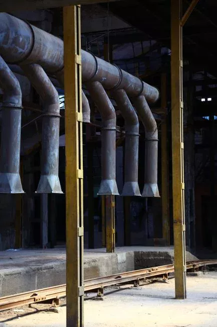
The forced-circulation loop is the engineering choice that makes MVR serviceable on scaling wastewaters. A centrifugal circulation pump is sized to push the liquid through the heater tubes at 2–4 m/s — a velocity high enough to sweep nascent crystals off the tube wall and prevent particulate fouling. Pump head sets the loop pressure above the saturation pressure at the separator, which suppresses nucleate boiling inside the tubes. The result is that the heater transfers sensible heat only; no vapor is generated inside the heat exchanger, and scale formation is dramatically reduced (ENCON, 2026).
Two heat-exchanger styles appear on MVR PFDs. Plate-and-frame units give the highest area per footprint and are the default on compact skids, but shell-and-tube is preferred where fouling tendency is high or where a mechanical cleaning window is needed. At the heater outlet, an orifice plate creates a controlled pressure drop: downstream pressure falls to roughly 0.2–0.5 bar abs for low-pressure MVR service, and the superheated liquid flashes on the low-pressure side. The two-phase mixture then enters the separation tank, where vapor disengages upward and concentrated liquid falls to the bottom. This is the single most important hydraulic feature of the diagram — without the orifice, there is no flash, and without the flash, there is no vapor to recompress.
Block 3 — Separation Tank, Vapor Compressor, and the Closed Loop
The separation tank is where the loop turns. Vapor disengages and rises through a demister pad to remove entrained droplets; concentrated liquid collects at the bottom and is discharged by pump or gravity as the concentrate stream. The clean vapor overhead is the suction of the vapor compressor. Two compressor families are in commercial service: rotary-lobe (Roots) blowers for smaller units and high-alloy centrifugal compressors for larger units, with duplex stainless steel as the standard wetted material for corrosive service (ENCON, 2026). Both options appear explicitly in standard MVR product offerings.
The compressor's job is to raise the vapor's saturation temperature by typically 8–15 °C — enough to establish a usable ΔT across the main heat exchanger so that the recompressed vapor can condense on the shell side and deliver its latent heat to the circulating stream. Compressing vapor to a slightly higher pressure costs roughly 1/20th the energy of generating fresh steam at the same conditions, which is the thermodynamic reason MVR is so efficient (Gotsu Mill, 2019). Closing the loop: compressor discharge vapor enters the main heat exchanger shell side, condenses, leaves as hot condensate, passes through the preheater to preheat incoming feed, and exits as cool distillate to the distillate tank. A small slipstream of vapor is vented to remove non-condensables, and a small make-up of live steam (or electric immersion) is used at start-up to bring the loop up to operating temperature. In steady state, no continuous live-steam input is required.
Stream-by-Stream Parameter Table
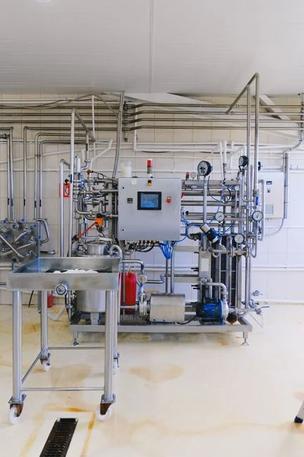
The table below uses ENCON's standard operating envelope — 500–1,350 gph (≈1.9–5.1 m³/h) for standard units, with custom builds above that — as the calibration point. Exact values depend on the wastewater's boiling-point elevation and the chosen compressor ΔT lift, so the numbers are indicative for a low-pressure MVR on a near-water feed.
| Stream | Source | Destination | Phase | Typical T (°C) | Typical P (bar abs) | Key Control |
|---|---|---|---|---|---|---|
| Feed | Plant influent | Feed tank | Liquid | 20–30 | Atmospheric | Level, conductivity, pH |
| Preheated feed | Preheat exchanger | Circulation loop | Liquid | 35–45 | 0.3–1.5 | Outlet temperature |
| Circulation loop (heater side) | Pump discharge | Heater inlet | Liquid | Saturation +3 to +5 | 0.8–2.0 | Flow (2–4 m/s) |
| Heater outlet | Main HX | Orifice plate | Subcooled liquid | Saturation +3 to +5 | 0.8–2.0 | ΔT across HX |
| Flashed two-phase | Orifice plate | Separator | Liquid + vapor | Saturation | 0.2–0.5 | Separator level |
| Separator vapor | Separator top | Demister → compressor | Saturated vapor | 55–75 (low-P) | 0.2–0.5 | Compressor suction T |
| Compressor suction | Demister | Compressor inlet | Saturated vapor | 55–75 | 0.2–0.5 | Surge margin |
| Compressor discharge | Compressor outlet | Main HX shell | Superheated vapor | +8 to +15 above suction | 0.4–1.0 | Discharge T, amp draw |
| Main HX condensate | Main HX shell | Preheater | Liquid | Saturation at shell P | 0.4–1.0 | Condensate level |
| Distillate | Preheater outlet | Distillate tank | Liquid | 30–45 | Atmospheric | Conductivity, flow |
| Concentrate | Separator bottom | Discharge / crystallizer | Liquid or slurry | 55–75 | 0.2–0.5 | Density, TSS, discharge valve |
MVR vs MEE vs Thermal Vapor Recompression
Before specifying a single pump, the engineer needs to decide which evaporator family fits the site. The choice is driven by steam availability, electricity cost, target capacity, and the wastewater's fouling tendency. The comparison below places MVR next to its two main alternatives — multi-effect evaporation (MEE) and thermal vapor recompression (TVR) — so the trade-offs are visible at a glance.
| Parameter | MEE | MVR (Mechanical) | TVR (Thermal) |
|---|---|---|---|
| Heat source | Live steam, multi-effect | Recompressed vapor (no live steam) | Live high-pressure steam via ejector |
| Compressor / driver | None | Rotary-lobe blower or centrifugal compressor (electric) | Steam-jet ejector (no moving parts) |
| Live steam required | Yes, continuous | Start-up only | Yes, motive steam |
| Energy use basis | Steam kg per kg water evaporated | Electricity kWh per kg water evaporated | Steam kg per kg water evaporated |
| Footprint | Large (multiple vessels) | Compact (single skid) | Medium |
| Best-fit wastewaters | Very large flows, dilute, non-scaling | Moderate flow, scaling or corrosive, where steam is costly or unavailable | Retrofit of existing steam-heated evaporators |
| CAPEX vs OPEX bias | Lower CAPEX, higher OPEX | Higher CAPEX, lower OPEX | Hybrid economics |
| Documented case | Baseline for Gotsu comparison | Gotsu Mill 2019: 13% energy cost cut, 111% output | Common in evaporator retrofits |
The Gotsu Mill 2019 case is the clearest published validation of the OPEX argument: Nippon Paper's Gotsu Mill selected an MVR evaporator over a new multi-effect vacuum evaporator for SP black liquor concentration and reported a 13% reduction in energy cost together with a 111% increase in pulp production versus the pre-retrofit baseline (Japan TAPPI Journal Vol. 74, No. 7, 2020). For plants evaluating MEE-to-MVR retrofit decisions in 2026, that data point sets the realistic expectation band for energy savings.
Failure Modes and What the PFD Doesn't Tell You
The block diagram is silent on the operating problems that consume most of the maintenance budget. Two failure modes from the Gotsu Mill start-up are well documented and worth carrying into any MVR spec: heater fouling from scale on the SP black liquor, which the mill mitigated by intensifying vapor-drain flushing, and compressor vibration on start-up, which was resolved by open cleaning and is now prevented by routine CIP (Japan TAPPI Journal Vol. 74, No. 7, 2020). Modern MVR skids ship with automated CIP cycles as standard, and that automation is the single largest reliability gain over first-generation units.
Generalizing from that case, scaling risk is highest in the heater and preheater, and the control loop is ΔT monitoring across the heat exchanger combined with antiscalant dosing at the feed and timed CIP cycles. A rising ΔT at constant compressor duty is the earliest reliable indicator of fouling. Compressor surge is the most damaging transient and the most expensive mechanical failure; surge control and VFD soft-start are standard on 2026 units, and the operator should never be allowed to throttle suction below the manufacturer's published minimum flow. Bearing temperature, vibration, and motor current should be trended continuously and integrated with the plant DCS rather than monitored only locally.
Sizing and 2026 Design Considerations
Translating the PFD into a working spec comes down to four drivers: feed flow in m³/h, target concentration factor, distillate purity, and the available energy source (electricity versus steam versus hybrid). Standard skid envelopes handle 500–1,350 gph, or roughly 1.9–5.1 m³/h, with custom builds covering larger flows; below that range, the unit economics start to favor a smaller falling-film or batch evaporator. Above it, MVR remains competitive against MEE on OPEX once electricity is cheap relative to steam and the plant has no spare boiler capacity (Gotsu Mill, 2019).
Material selection is driven by chloride, pH, and TSS. 2205 duplex handles most brackish and mildly corrosive streams; 254 SMO or titanium is specified for high-chloride concentrates above roughly 1,000 mg/L Cl⁻; graphite blocks are used where heat transfer surface must remain passive in aggressive acid service. Automation scope in 2026 typically includes PLC + HMI, automatic CIP, remote telemetry, and integration with the plant DCS via Ethernet/IP or Modbus TCP, and the antiscalant and pH control on the MVR feed line should be specified as part of the same skid to keep the dosing logic inside one control narrative.
Frequently Asked Questions
What makes MVR different from MEE in a process flow diagram?
An MVR PFD shows a single closed vapor loop driven by a compressor, while an MEE PFD shows a train of effects each heated by vapor from the previous effect and ultimately by live steam. MVR's energy input is mechanical (compressor work) rather than thermal (live steam), which is why the Gotsu Mill 2019 retrofit recorded a 13% energy-cost reduction versus a new multi-effect vacuum evaporator.
What does the vapor compressor actually do in an MVR evaporator?
The compressor raises the saturation temperature of the secondary vapor by typically 8–15 °C so the recompressed vapor can condense on the shell side of the main heat exchanger and deliver its latent heat to the circulating stream. Rotary-lobe blowers are used on smaller units and centrifugal compressors on larger units, with the compressor as the only continuous energy input in steady state.
Where does the closed loop close on the PFD?
The loop closes at the main heat exchanger: compressor discharge vapor enters the shell side, condenses, leaves as hot condensate, flows through the preheat exchanger to warm the incoming feed, and exits as cool distillate to the distillate tank. A small vent stream removes non-condensables, and a small start-up steam input brings the system to operating temperature.
Which wastewaters are not a good fit for MVR?
Very dilute streams below about 1% TDS are usually uneconomic because the energy saved per kilogram of water evaporated is small relative to fixed compressor power. Streams with high non-condensable gas loading (for example, ammonia- or VOC-laden wastewaters) can also be difficult because the vent rate becomes large and the compressor surge margin shrinks. For those feeds, MEE with a forward-feed arrangement or a stripping pretreatment upstream of MVR is usually a better fit.
What is the typical payback driver for an MVR installation?
The dominant payback driver is the displaced cost of hauling or treating the wastewater. Operating costs in published commercial data run as low as $0.01–0.02 per gallon of distillate, and the same source reports up to a 95% reduction in wastewater disposal costs (ENCON, 2026). For plants already paying for off-site disposal, the avoided hauling cost typically pays back the CAPEX in 1–3 years, with the 13% energy-cost reduction at Gotsu Mill as a reasonable floor for the OPEX improvement versus MEE.
Related Equipment
- DAF pre-concentration upstream of an MVR evaporator — specifications, capacity range, and technical data