Why MEE Installation and Commissioning Is a Distinct Engineering Discipline
Multiple effect evaporator (MEE) installation and commissioning is a phased engineering protocol that converts a fabricated evaporator into a ZLD-ready asset: site and civil readiness, mechanical alignment of shells and tube bundles, piping and instrument installation, vacuum integrity testing (target leak rate below 0.5 mbar/h on the last effect), water batching, steam balance, and a 72-hour performance acceptance test at design evaporation load. Acceptance typically requires steam economy within ±5% of design (e.g., 2.8–3.2 kg vapor per kg live steam for a 4-effect unit) and condensate conductivity below 50 µS/cm for water-recovery duty.
An MEE is a vessel, a heat exchanger, and a vacuum system stacked into one pressure cascade — and that is what makes it unforgiving. Vapor from effect N-1 boils feed in effect N at progressively lower pressure, with live steam entering the first effect (per Distington S2 and the MDPI S4 sugar-mill simulation). A single vacuum leak on the last effect, a steam pressure deviation of 20 kPa on the first, or a misaligned condensate trap collapses economy by 30–40% and pushes concentrate quality out of spec. Commissioning scope spans chemical, pharmaceutical, textile, and food-processing ZLD plants (per Distington S2), each with its own carryover and fouling profile.
Reference throughput benchmarks from the MDPI S4 simulation are realistic design-point anchors a project engineer can quote back to an EPC contractor: 125 kg/s inlet flow, 15% inlet → 70% outlet concentration, last-effect pressure 16 kPa, ambient 30 °C, first-effect steam at 200 kPa. Forward-feed consumes 43.45 kg/s of extracted steam at 185.5 kPa for that duty; backward-feed consumes 30.62 kg/s at 151.3 kPa and gains 3.2% cogeneration efficiency. Pin your acceptance numbers to these published values and your contractor cannot move the goalposts.
Phase 1 — Pre-Shipment Factory Acceptance Test (FAT)
The cheapest problems to fix are the ones caught in the shop. A structured FAT protects the buyer from signing crates that contain rework.
- Hydrostatically test each effect shell and tube bundle to 1.5× design pressure for 30 minutes; record pressure decay and visually inspect all welds and tube-to-tube-sheet joints.
- Confirm every nozzle orientation against the general arrangement drawing — nozzle mismatch is the single largest source of on-site re-work.
- Verify calibration of pressure transmitters, RTDs, level switches, and conductivity cells; supplier must ship NIST-traceable certs.
- Run a cold mechanical check: rotate feed and condensate pumps, stroke the vacuum pump set, bump blowers, and verify every PLC and SCADA I/O point (per the WTE Infra S5 automation scope).
- Issue a signed FAT report with a closed punchlist; any open item becomes a hold-point in the on-site SAT.
| FAT Item | Acceptance Criterion | Document Required |
|---|---|---|
| Shell hydrostatic test | 1.5× design pressure, 30 min hold, zero visible weep | Pressure vs. time chart |
| Tube bundle hydrostatic test | 1.5× design pressure, 30 min hold | Pressure vs. time chart |
| Nozzle orientation | Match GA drawing, ±5 mm | Signed GA overlay |
| Instrument calibration | NIST-traceable certs in O&M manual | Calibration certificates |
| Cold mechanical rotation | All rotating equipment free, correct rotation | Rotation checklist |
| PLC/SCADA I/O | 100% point-to-point verified | I/O checkout sheet |
Phase 2 — Civil, Foundation, and Structural Readiness
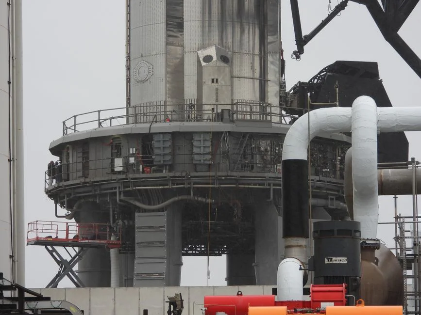
Civil work that is not finished when the truck arrives is the most common schedule-killer on MEE projects. Build the readiness list into the purchase order, not into the field crew's improvisation.
Foundation concrete must cure a minimum of 14 days before setting the skid; verify the anchor-bolt template against the supplier's GA drawing to a typical tolerance of ±5 mm. Confirm structural support for the heaviest single lift — a 4-effect MEE first-effect shell can exceed 25 tonnes when fully fitted. Maintain at least 1.2 m of clear access on all four sides of the skid for tube-bundle pull-out and tube-sheet cleaning, because a bundle that cannot be removed is a bundle that cannot be maintained. Provide task lighting, floor drainage, and a dedicated electrical isolator within 5 m of the MCC panel so commissioning electricians can lock out safely.
Phase 3 — Mechanical Installation, Alignment, and Piping
Mechanical installation is where fabrication tolerances meet site reality. Treat the evaporator as a precision instrument, not a tank.
Set the skid on grouted baseplates and check level across the tube sheet to within 1 mm/m before the final grout pour — a tilted first effect biases the entire cascade. Route steam, vapor, condensate, feed, concentrate, and vacuum lines with a minimum 1:200 slope toward the condensate flash tank to prevent water hammer and waterlogging in vapor lines. Install flexible bellows on large-bore steam and vapor lines; first heat-up will grow the first-effect shell by 10–25 mm and a rigid pipe will crack the nozzle. Pressure-test all piping to 1.25× design pressure using nitrogen or demineralized water — never compressed air on the vacuum side, because an air-side failure under vacuum is a safety incident. Wire instrumentation for differential pressure across each effect, shell-side temperature, feed and concentrate conductivity, and vapor-space temperature, and integrate chemical feed points with an automatic chemical dosing system sized for anti-scalant and anti-foam service. The piping layout should match the same engineering rigor used in any AOP system installation and commissioning protocol, since both rely on accurate flow and pressure control at every tie-in.
Phase 4 — Vacuum Integrity and Leak Testing
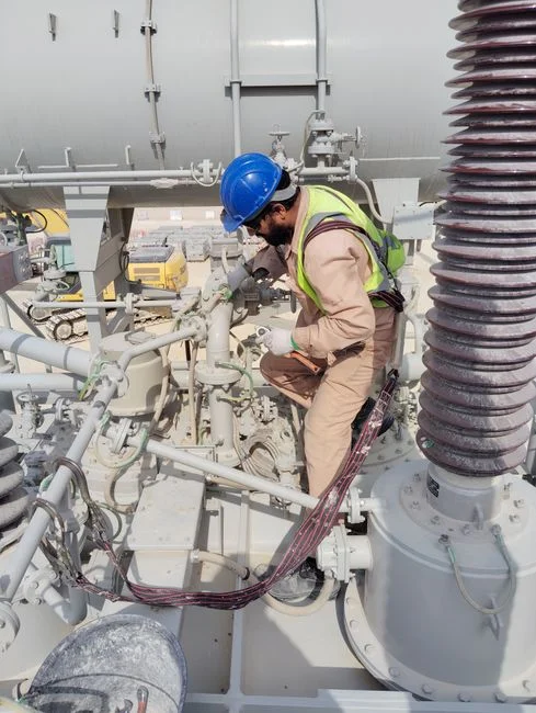
Vacuum integrity is the single most critical MEE commissioning step. A leaky last effect is a 30–40% penalty on live steam economy and there is no operating fix — only a mechanical one.
Pull the last effect to design vacuum, typically 16 kPa absolute per the MDPI S4 reference case, using the dedicated vacuum pump set. Hold vacuum for 24 hours and record the pressure-rise curve. The pass criterion is a leak rate ≤0.5 mbar/h on a leak-tight system, relaxing to ≤1.0 mbar/h on systems with internal volume above 100 m³. If the threshold is exceeded, isolate each flange with a helium sniffer or run a soap-bubble test on the positive-pressure sections upstream. The most common leak sources are condenser tube-to-tube-sheet joints, vacuum-pump seal water connections, level-sight-glass gaskets, and the barometric leg seal. Do not proceed to steam commissioning until the vacuum test passes — every hour saved here is paid back tenfold in live-steam costs once the plant is running. Skipping this step is one of the costliest mistakes a commissioning team can make and shows up immediately in the municipal sewage plant operating cost 2026 OPEX breakdown logic that applies equally to industrial ZLD OPEX.
Phase 5 — Water Batching and Steam Commissioning
Water commissioning is the first live but safe run — no real feed, no real fouling risk, and full access to tune the cascade before effluent enters the system.
Charge each effect with demineralized water to the normal operating level and verify level control loops and high-level trips. Admit live steam slowly into the first effect, ramping at no more than 1 °C/min to avoid thermal shock to tubes and tube sheets — a faster ramp will crack a tube sheet on a cold bundle. Establish the pressure cascade one effect at a time: first effect at 200 kPa, second at approximately 80 kPa, third at approximately 30 kPa, and the last effect at 16 kPa, per the MDPI S4 forward-feed reference. Check condensate flow and temperature at each effect; condensate superheat above 5 °C indicates live steam leaking into the product side, which is a tube failure and a hard stop. Run for 4–6 hours on water, then record steam economy, condensate conductivity (should sit below 10 µS/cm on DM water), and vacuum stability. Any drift here is a control or instrument problem, not a process problem, and it is cheap to fix now.
Phase 6 — Performance Acceptance Test on Real Feed
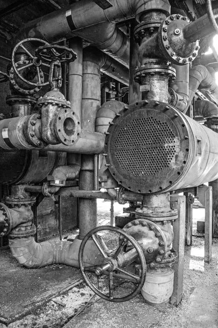
The 72-hour performance test is the contractual pivot. The numbers below are the ones a supplier cannot dispute if the test is run at design feed rate and design inlet/outlet concentration.
| Parameter | Design Target (4-effect) | Pass Window | Reference |
|---|---|---|---|
| Steam economy (kg vapor / kg live steam) | 3.0 | 2.8–3.2 (±5%) | 4-effect industry typical |
| Steam economy, 5-effect | 3.75 | 3.5–4.0 (±5%) | 5-effect industry typical |
| Condensate conductivity | < 30 µS/cm | < 50 µS/cm | ZLD water-recovery spec |
| Specific steam, forward-feed | 43.45 kg/s @ 125 kg/s feed | ±5% | MDPI S4 simulation |
| Specific steam, backward-feed | 30.62 kg/s @ 125 kg/s feed | ±5% | MDPI S4 simulation |
| Last-effect pressure | 16 kPa | 14–18 kPa | MDPI S4 reference |
| Test duration | 72 h continuous | No interruption > 30 min | Industry standard |
Record evaporation rate per effect, temperature profile, and pressure profile every 30 minutes. Trend for 72 continuous hours. A backward-feed MEE is supplied only if the supplier can hit the lower specific-steam number (30.62 kg/s); otherwise the test fails on steam economy even if evaporation rate is correct.
Phase 7 — Common First-Month Failures and How to Prevent Them
Most first-month MEE problems are predictable. The five below account for the majority of warranty calls and each has a known root cause and a known prevention.
| Symptom | Likely Root Cause | Prevention / Fix |
|---|---|---|
| Carryover into condensate (conductivity rising) | Demister choke or feed preheater overshoot | Tune feed preheater to within ±3 °C of setpoint; inspect demister pad |
| Vacuum loss on last effect | Undersized vacuum pump or cooling water > 32 °C | Re-rate pump against manufacturer curve; trim cooling-tower approach |
| First-effect tube fouling | Hardness or silica scaling on feed side | Install online conductivity and a CIP loop; place a plate and frame filter press upstream for solids removal |
| Foaming in intermediate effects | Surfactant or organic load in feed | Integrate defoamer injection through an automatic chemical dosing system |
| Steam economy decline | Condensate trap failure or non-condensable buildup | Test traps weekly; purge non-condensables every 4 h in first month |
Phase 8 — Handover Documentation and Operator Training
A clean handover is what stops the plant from regressing into commissioning problems two months after the EPC crew leaves. Treat the documentation package as a deliverable on the same critical path as the equipment.
Deliver as-built GA drawings, P&IDs, wiring diagrams, instrument loop sheets, PLC and SCADA backups, and material certificates. Compile the commissioning dossier with hydrostatic test reports, vacuum test logs, the 72-hour performance test report with KPIs, and the closed punchlist. Train operators on the startup sequence, the normal operating window, emergency shutdown, basic troubleshooting, and the CIP procedure — each on a simulator or live panel, not on a slide deck. Establish a 30-day warranty period with on-call engineering support and a quarterly performance review for the first year. Hand over the recommended spare parts list: nozzles, sight-glass gaskets, vacuum-pump seal kits, and one set of demister pads. The same discipline applies in any constructed wetland installation and commissioning protocol — handover quality sets the operating cost trajectory for the next decade.
Frequently Asked Questions
How long does MEE installation and commissioning take on site?
Typically 4–8 weeks for a 3–5 effect unit, driven mainly by civil readiness. A clean foundation and pre-laid pipe racks cut this to the lower end; late anchor bolts or missing MCC power push it to the upper end.
What is the typical steam economy of a 4-effect MEE?
2.8–3.2 kg vapor per kg live steam at design feed and concentration. A 5-effect unit runs 3.5–4.0. Deviation beyond ±5% from the design point triggers an investigation under the performance acceptance clause.
What vacuum leak rate is acceptable?
≤0.5 mbar/h on the last effect after a 24-hour hold for a leak-tight system, and ≤1.0 mbar/h for systems with internal volume above 100 m³. Anything beyond these thresholds blocks steam commissioning.
Can an existing MEE be upgraded from forward-feed to backward-feed?
Technically yes, but it requires new piping for two extracted-steam pressures and a revised control logic. The economics rarely justify a retrofit; backward-feed is usually a design choice made at purchase.
When should ATFD follow the MEE?
When the final concentrate TDS exceeds the saturation limits of the MEE and the slurry becomes pumpable but not boilable. An Agitated Thin Film Dryer polishes the solids to a landfill-acceptable or recoverable form, and it sits downstream of the MEE in any ZLD train.