What 'Constructed Wetland Installation and Commissioning' Actually Covers
Constructed wetland installation covers the physical construction of the treatment cell from subgrade compaction through media placement and emergent macrophyte planting, while commissioning is the controlled startup that proves the cell meets its hydraulic and biological performance targets before the system is handed over to the operator. The two activities are sequential and inseparable on a contractor's schedule: every construction phase closes with a documented acceptance test before the next begins, because field deviations in slope, liner integrity, media gradation, or water-level control all degrade the discharge numbers the regulator and the client engineer will measure later.
The protocol diverges at the liner and water-level control step depending on whether the cell is a horizontal subsurface flow (HSSF), vertical subsurface flow (VF), vertical surface flow (VSF), or free water surface (FWS) system, per the MDPI classification (MDPI Processes 9(11):1917, 2021-10). SSF systems keep water 1–3 inches below the media surface; FWS systems flood the surface. The history of the technology is a cautionary tale: in the UK, the Constructed Wetland Association was formed in October 1999 specifically because poorly built reed beds were failing in service, a problem that drove the trade body to build a database now containing more than 1,000 UK systems (Springer, Cooper 2008).
Five removal-mechanism zones drive every construction decision: settling of suspended solids, microbial biofilm growth on the media surface, plant root uptake of nitrogen and phosphorus, sorption onto substrate (especially for metals), and photodegradation at the surface. Each construction step protects a specific mechanism — a misplaced low spot kills anaerobic biofilm function, a fines-loaded gravel bed chokes sorption sites, a flooded surface blocks oxygen transfer to roots.
Phase 1 — Earthworks, Subgrade, and Liner Selection
Phase 1 begins with subgrade compaction to design elevation at ≤1% cross-fall, and the longitudinal bed slope must finish between 0% and 1% (0 to 1 ft of drop per 100 ft of length) so gravity drives plug flow without short-circuiting (UNL NebGuide G1474, 2008). The length-to-width ratio of the cell must read 2:1 to 3:1 — for a 300 ft² cell, 30 ft × 10 ft is acceptable because 30/10 = 3:1. Survey the finished subgrade with a level before liner deployment and reject any deviation greater than ±0.5% from the design drawing.
Liner selection is the highest-stakes field decision. Four options are all technically acceptable: compacted native clay, bentonite-amended clay, reinforced concrete, or a synthetic geomembrane. Limestone-bearing media is explicitly rejected as the cell substrate because it breaks down under the acidic conditions that develop inside a working wetland (UNL NebGuide G1474, 2008). Sides of the cell must finish at least 6 inches above surrounding grade to exclude stormwater runoff; in freezing climates, plan to insulate the top 18 to 24 inches of the cell perimeter to protect emergent plant roots and tubers through winter (UNL NebGuide G1474, 2008).
| Liner Option | Typical Thickness / Spec | Field Acceptance Test | Reject If |
|---|---|---|---|
| Compacted native clay | ≥12 in compacted lift, permeability ≤1×10⁻⁷ cm/s | Sand cone or nuclear density test per ASTM D6938 | Clays with high organic content; permeability test fails |
| Bentonite-amended clay | 6–8% bentonite by dry weight, mixed in 6 in lifts | Pad test for swell; permeability verification | Unmixed streaks visible; ponded water infiltrates within 30 min |
| Cast-in-place concrete | 4 in minimum, 3000 psi, #4 rebar @ 12 in o.c. | Slump test on delivery; crack inspection at 28 days | Hairline cracking >1/16 in width; honeycombing at cold joints |
| HDPE/LLDPE geomembrane | 40–60 mil, textured, double-welded seams | Air pressure test on seams (ASTM D5820); visual scan | Any seam failure on pressure test; puncture >1/4 in diameter |
Phase 2 — Hydraulic Controls, Inlet/Outlet, and Distribution Piping
Connect the cell to the downstream polishing pond, drainfield, or habitat pond with a 4-inch diameter Schedule 40 thermoplastic PVC pipe (or equivalent), laid at a minimum 0.5% slope (1/2 ft per 100 ft) so gravity drives flow even at low dosing rates (UNL NebGuide G1474, 2008). Solvent-welded joints are preferred over gasketed joints for buried service because gaskets can shift during media placement.
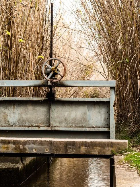
Install an adjustable water-level control sump at the outlet as the single most-commissioned hydraulic fitting. The sump is a vertical riser pipe with a removable cap or a slotted weir that lets the operator set the free-water surface 1 to 3 inches below the top of the gravel. This control determines whether the cell runs anaerobic (too low) or odor-producing and mosquito-friendly (too high). In residential and light-commercial cells, the sump is the operator's primary tool; in industrial cells receiving a higher organic load, the sump must be sized for a wider adjustment range because influent BOD swings are larger.
Inlet distribution is the second hydraulic control that gets verified during the wet commissioning test. Use a manifold of perforated pipe or a distribution chamber that spans the full inlet width so effluent enters the cell as a uniform sheet. For VF beds, confirm even surface dosing during the first wet run — dry patches mean later short-circuiting. When the wetland sits above the homesite or factory pad, specify a dosing pump with a documented duty cycle (cycles/day, run time per cycle) and a maintenance plan: energy draw, seal life, and service interval are real hand-off items that the client engineer will inherit (UNL NebGuide G1474, 2008). Upstream screening with a rotary mechanical bar screen protects the distribution network from rag and debris carryover.
Phase 3 — Media Placement: Gradation, Washing, and Depth Control
The most common field failure in wetland construction is fines migration into the bed, which clogs the distribution network and chokes the sorption sites the design relies on for metal and phosphorus removal. Specify graded gravel or another porous, corrosion-resistant material that is free of silt and clay; reject any load that contains visible fines or limestone fragments at the point of delivery (UNL NebGuide G1474, 2008).
Wash media on a hard surface or screening deck before placement — a single unwashed load can introduce enough silt to drop porosity by 15–20% within the first month of operation. Place media in 6–8 inch lifts and level with a rake between lifts. Eliminate low spots that will pond wastewater and generate odor, and high spots that will short-circuit flow. The finished surface should be within ±0.5 inch of design elevation across the full cell footprint, verifiable with a straightedge and string line.
| System Type | Common Substrate | Typical Gradation | Target Pollutant |
|---|---|---|---|
| HSSF | Washed coarse gravel | 10–30 mm | BOD, TSS, nitrification |
| VF | Washed sand over gravel support layer | 0.2–2 mm sand; 5–20 mm gravel | Ammonia (nitrification), TSS |
| FWS | Native soil or sandy loam | Site-specific | TSS, some metals |
| HF / industrial VF-FWS | Zeolite, calcite, BOF slag, activated carbon, lightweight aggregate | Per design (MDPI Processes 9(11):1917, 2021-10) | TP, TN, sulfate, heavy metals (Cd, Pb, Cr, Ni, Fe) |
Industrial polishing cells treating metal-bearing or petroleum wastewater commonly use zeolite for ammonia exchange, calcite for pH buffering and phosphorus precipitation, and basic oxygen furnace slag or activated carbon for trace organics and refractory metals (MDPI Processes 9(11):1917, 2021-10). Substrate choice is driven by influent chemistry — running a metals-loaded stream through a coarse-gravel HSSF without a sorption media layer is a design error the contractor cannot fix in the field.
Phase 4 — Planting and the 4–12 Week Plant Establishment Period
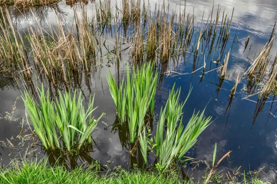
Plant emergent macrophytes at the density specified in the design — typically 2–4 plants per m² for cattails (Typha), bulrushes (Schoenoplectus), and common reeds (Phragmites) in temperate systems. For high-strength industrial flow, vertical surface flow constructed wetlands (VSF-CW) vegetated with Eichhornia crassipes (water hyacinth) achieve documented removals on petroleum refinery secondary effluent, including 94.6% BOD₅, 80.2% COD, 92.6% TPH, 99.4% oil and grease, and 92–95% removal of Cd, Pb, Cr, Fe, and Ni (MDPI Processes 9(11):1917, 2021-10). These are not guarantees — they are design-intent benchmarks the contractor should put in the commissioning report so the client and the regulator see the same reference numbers.
The establishment window runs 4 to 12 weeks depending on climate, species, and planting stock. During this period, protect young plants with a 1-foot high, 1-inch mesh woven-wire fence to exclude rabbits and wild rodents (UNL NebGuide G1474, 2008). Maintain the water level within the 1–3 inch submergence target throughout establishment — lower levels can dry or freeze roots, while levels closer to the surface cause odor. Do not declare the system "failed" at week 3 because biofilm and root systems are still maturing; expect COD/BOD removal at week 4 to be roughly 60–70% of the design target and to climb through week 12 as biofilm biomass builds.
Remove volunteer trees, fescue, and brome during establishment because they outcompete the planted macrophytes. Manual removal is preferred; spot-treat with an approved herbicide on calm days if the infestation is too large to pull (UNL NebGuide G1474, 2008). For cold-climate cells, leave at least 12 inches of standing plant material above the media surface going into winter — the stubble collects insulating snow and supports spring regrowth.
Performance Benchmarks to Put in the Commissioning Report
The discharge application, the client engineer's sign-off package, and the regulator submission should all rest on the same peer-reviewed numbers. Document the following design-intent benchmarks so the operating party knows what the system is expected to deliver once biofilm and root systems mature:
- Duckweed-microalgae constructed wetland (DM-CW): COD 68%, BOD 71%, ammoniacal nitrogen 66%, total phosphorus 21.5%, total nitrogen 68.5%, fecal coliforms 47.2% (MDPI Processes 9(11):1917, 2021-10).
- VSF-CW with Eichhornia crassipes on petroleum refinery secondary effluent: turbidity 91.5%, BOD₅ 94.6%, COD 80.2%, TPH 92.6%, oil/grease 99.4%, Cd 94%, Pb 92.5%, Cr 93%, Fe 94.8%, Ni 92.2% (MDPI Processes 9(11):1917, 2021-10).
- Heavy-metal mass removal across wetland types ranges 27–99%; long-term internal sequestration averages ~7.6 kg/ha/year, or 54% of influent metals load (MDPI Processes 9(11):1917, 2021-10).
Frame these as design-intent benchmarks, not guaranteed discharge numbers. Actual performance depends on hydraulic retention time verification, ambient temperature, influent variability, and whether the operator maintains the water level in the 1–3 inch submergence band. For sites where the wetland is being added downstream of a buried package sewage treatment plant, the wetland acts as a tertiary polishing step and the combined removal across the train will exceed either unit alone.
Acceptance Test Checklist — What to Sign Off Before Handover
The handover meeting is where the contractor and the client engineer sign line by line that each design value was verified in the field. Walk the cell with the checklist, photograph each test, and file the package with the commissioning report.
| Design Parameter | Acceptance Criterion | Field Verification Method | Pass / Fail |
|---|---|---|---|
| L:W ratio | 2:1 to 3:1 | Tape measure, both axes | |
| Bed slope | 0–1% longitudinal (UNL NebGuide G1474, 2008) | Survey level, 3 stations min | |
| HRT (wet test) | 2–3 days for SSF (UNL NebGuide G1474, 2008) | Tracer or bucket-and-stopwatch at outlet | |
| Water level vs. media surface | 1–3 in below gravel | Staff-gauge reading, photograph | |
| Surface ponding | None above 1–3 in submergence | Visual after 24 h dosing at design flow | |
| Downstream pond seepage | ≤1/8 in per day (UNL NebGuide G1474, 2008) | Evaporation pan correction, 7-day test | |
| Baseline influent/effluent | BOD, TSS, NH₃-N, site-specific metals | Grab samples, lab analysis, week 12 of startup |
Dose clean water at the design flow rate during the wet test, measure the time for the first slug to appear at the outlet, and confirm no surface ponding. Set the outlet water-level control sump so the surface reads 1–3 inches below the gravel; document with a photograph and a staff-gauge reading. Confirm seepage at any downstream pond does not exceed 1/8 inch per day, and pull the baseline influent/effluent sample set before declaring the system "in service." For projects downstream of a lamella clarifier installation and commissioning protocol, the wetland picks up the clarifier's settled stream, and the contractor should coordinate the dosing schedule so both unit tests are witnessed in the same week.
Frequently Asked Questions
How long does commissioning take from first dose to sign-off?
Plan on 4 to 12 weeks from the first dose to handover. The first 1–2 weeks cover the hydraulic wet test (HRT verification, water-level sump adjustment, seepage check); weeks 2–12 cover the plant establishment window during which biofilm and root systems mature and the startup curve climbs toward design-intent removal rates (UNL NebGuide G1474, 2008; MDPI Processes 9(11):1917, 2021-10).
What hydraulic retention time should the wet test verify?
Verify a 2–3 day HRT for SSF systems (UNL NebGuide G1474, 2008). Use a tracer slug or a bucket-and-stopwatch timing at the outlet during the first wet run; if measured HRT is below 2 days, the bed is short-circuiting and the contractor must correct the inlet distribution or slope before handover.
What should I do if water surfaces above the gravel during the wet test?
Lower the outlet water-level control sump to drop the free-water surface back into the 1–3 inch submergence band. If ponding persists, the cell has a low spot that must be raked level and topped with washed media, because persistent surface ponding generates odor and blocks oxygen transfer to plant roots (UNL NebGuide G1474, 2008).
Is limestone media acceptable in the wetland cell?
No. Limestone breaks down under the acidic conditions that develop inside a working wetland, which degrades the substrate and releases dissolved solids into the discharge (UNL NebGuide G1474, 2008). Specify washed gravel, sand, zeolite, calcite (non-limestone), BOF slag, or activated carbon depending on the target pollutant.
How do I handle startup in a freezing climate?
Insulate the top 18–24 inches of the cell perimeter during construction (UNL NebGuide G1474, 2008), lower the water level slightly to protect roots from ice damage, and leave at least 12 inches of standing plant material above the media surface going into winter. Do not shut the system down during cold months if continuous flow is available; intermittent loading causes freeze-thaw damage to the liner and to the plant rhizomes.