
What AOP System Installation and Commissioning Actually Covers in 2026
AOP system installation and commissioning is the sequenced handover of an advanced oxidation reactor — typically H2O2/UV, O3/H2O2 (peroxone), Fenton, or catalytic AOP — from civil completion to validated hydroxyl-radical operation. The 2026 protocol runs in three stages: (1) pre-installation site and safety readiness, (2) cold mechanical commissioning without feed, and (3) hot performance commissioning that ramps oxidant dose, validates hydroxyl-radical CT, and confirms residual-quench targets before the 7-day performance acceptance test is signed off.
Advanced oxidation is, at its core, a •OH-radical-generating process. Whether the radicals are produced by photolysis of hydrogen peroxide, ozone-hydrogen peroxide synergy, Fenton chemistry, or a heterogeneous catalyst, the commissioning criteria are radically different from those used in a biological oxidation ditch. A biological basin is signed off on mixed-liquor velocity (0.25–0.35 m/s), MLSS (1,500–5,000 mg/L), and SRT (12–24 days for nitrification) per the EPA 832-F-00-013 reference framework. An AOP skid is signed off on hydroxyl-radical exposure, oxidant stoichiometry, and residual-quench performance. The four reactor configurations a process engineer typically receives are: H2O2/UV for trace organics, O3/H2O2 for color and COD reduction, Fenton for high-strength COD, and catalytic AOP for refractory TOC.
The 2026 trend tightens this requirement. Tighter discharge limits for COD, color, and micropollutants across textile, pharmaceutical, and landfill leachate operations are pushing more AOP skids downstream of biological treatment. That means the AOP commissioning protocol must explicitly reconcile with the upstream basin effluent baseline — the AOP does not see raw influent; it sees a partially treated stream whose alkalinity, chloride, and residual organics determine whether the radical yield will meet design.
Pre-Installation Site Readiness: The Gate Most AOP Projects Skip
Most AOP commissioning failures that surface in the first 30 days were lost at the civil-to-mechanical handover, before a single kilogram of reagent was ever loaded. Walk the readiness gates in the table below before the skid is delivered.
The civil scope begins with a bunded concrete plinth sized for 110% of the largest H2O2 storage volume and a neutralization pit sized for the largest single reagent tank, with floor drains routed to the quench tank rather than the storm drain. H2O2 storage requires a dedicated HDPE or stainless-316 tank, vented, physically separated from organics and incompatible materials, with an eyewash within 10 m and a continuous 30-minute water supply per ANSI Z358.1 (2025-08 guidance remains the current North American reference).
The ozone generator room needs forced ventilation delivering at least 6 air changes per hour, with a continuous ozone monitor calibrated to alarm at 0.1 ppmv and to trip the generator at 0.3 ppmv per OSHA 29 CFR 1910.1000. UV lamp electrical supply must come from a dedicated circuit with ground-fault protection; lamps are installed in the reactor housing before energising, and the lamp-hour counter baseline is recorded at the install walk-down so the warranty window is defensible. The EPC handover package — as-built P&ID, calibrated instrument certificates, and MSDS for every reagent — is the document set auditors examine first. A missing MSDS or a stale calibration certificate will halt the cold-commissioning gate on day one.
Mechanical Installation: Skid Placement, Piping, and Instrument Mapping
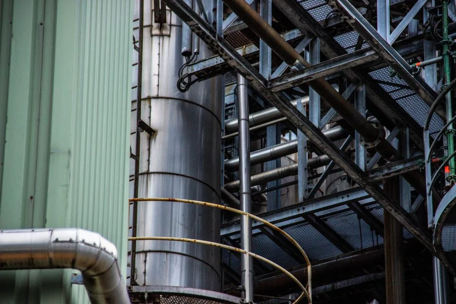
The mechanical sign-off is the gate between civil completion and any water touching the reactor. Get the placement, the pipework, and the instrument map right, and the hot commissioning ramp becomes a controlled exercise; get them wrong, and you fight chemistry for the next six months.
Level the skid to within 2 mm/m, anchor it to a vibration-isolated plinth when a UV reactor is on the skid, and leave at least 600 mm clearance on all four sides for service access and lamp replacement. Pipework must use oxidizer-compatible materials — PVDF, PP, or SS316 — for every H2O2 line. Black steel, copper, and brass are forbidden in the H2O2 wetted path; catalytic decomposition on copper and brass surfaces is the single most common premature-failure cause on Fenton and H2O2/UV skids. Pump alignment follows the Metcalf & Eddy-grade mechanical-installation practice used across industrial water treatment: shaft alignment within 0.05 mm, with flexible connectors on suction and discharge to dampen vibration. The 1/16-inch (1.6 mm) misalignment rule that recurs in packaged-plant guides remains the engineering baseline because it is the threshold above which bearing L10 life drops below design.
Instrumentation must be specified, located, and calibrated before hot commissioning. The minimum mapping is: pH probe on the feed line (range 2–12, temperature-compensated), ORP probe downstream of the reactor to confirm oxidant exposure, H2O2 residual probe on the discharge to gate the quench step, and flow meters on every oxidant dosing line. All calibration certificates must be dated within 30 days of commissioning. For the upstream solids-removal stage that protects the AOP from catalyst-bed blinding, follow the lamella clarifier commissioning protocol for the upstream stage, and the aeration system design guide when the AOP polish follows a biological step.
AOP Operating Parameters: The 2026 Reference Table
The table below consolidates the engineering-recommended operating windows for the four AOP configurations a process engineer will encounter in 2026. Use it as the print-and-pin reference at the commissioning site. Site-specific confirmation against the actual influent is mandatory; these are starting windows, not guarantees.
| Parameter | H2O2/UV | O3/H2O2 (Peroxone) | Fenton / Photo-Fenton | Catalytic AOP |
|---|---|---|---|---|
| H2O2 dose | 50–500 mg/L | Co-oxidant (H2O2:O3 molar 0.3–0.5) | To H2O2:Fe molar 5–10 | Per catalyst OEM |
| Oxidant ratio | — | 1–5 mg O3/mg COD | Fe²⁺ 50–200 mg/L | — |
| pH window | 6.5–8.5 | 6.5–8.5 | 2.5–3.5 | 5–9 |
| UV dose | 30–60 mJ/cm² | — | Optional photo assist | — |
| Contact / HRT | 5–20 min | 10–30 min | 30–60 min | Catalyst bed CT 10–30 min |
| Typical COD removal | 60–90% | 60–90% | 70–95% | 50–80% |
| Typical color removal | ≥95% | ≥95% | ≥95% | 70–90% |
| Typical TOC removal | 50–70% | 50–70% | 60–80% | 50–80% |
| Critical interlock | Lamp enclosure interlock; lamp-hour counter | Off-gas O3 destruction ≤ 0.1 ppmv at stack | H2O2 storage ≤ 30 °C; pH upper-limit trip | Bed ΔP trip; LEL on vented area |
Safety interlocks deserve their own line in the pre-commissioning checklist. H2O2 storage temperature must stay ≤ 30 °C to prevent thermal runaway; ozone off-gas destruction must hold stack concentration ≤ 0.1 ppmv at all operating loads; the UV lamp enclosure must be interlocked so the lamps cannot energise with the housing open; and an LEL detector must cover any area where H2 could accumulate from catalytic side-reactions. The 7-day performance acceptance structure follows the EPA 832-F-00-013 composite-sampling approach used for biological plants, but with the test parameters adapted from BOD/TSS to COD, color, and TOC because AOPs are not biological reactors.
Cold Commissioning: Energise Without Oxidant, Prove the Mechanical Heart
Cold commissioning is the dry-run phase where wiring, rotation, and interlocks are validated before any hazardous reagent is introduced. Skipping this stage is the single most common root cause of hot-commissioning chemical incidents.
Run the test sequence in this order: verify rotation on every pump, the UV reactor blower, and the ozone generator cooling water; confirm every valve actuates against the I/O list with the correct fail-safe direction; and validate every alarm and interlock end-to-end with a documented test sheet. Leak-test the H2O2 and O3 pipework at 1.5× design pressure for 30 minutes with no pressure drop — the same 30-minute integrity-test window used across packaged-plant commissioning guides, and the lowest-cost insurance on the project. A pressure drop larger than 1% in 30 minutes means a fitting, a weld, or an O-ring has to come out before hot work begins.
Calibrate the analytical loop with clean air and buffer standards: pH probe air-cal within 0.05 pH units against pH 4 and pH 7 buffers, ORP probe air-cal within 5 mV against a 220 mV quinhydrone standard, H2O2 residual analyser verified against a laboratory standard at 1 mg/L and 10 mg/L, and the ozone analyser confirmed to read zero on clean air. Every row of the cold-commissioning checklist must carry a name and a date — the same handover-defensibility standard EPA 832-F-00-013 calls out for biological plants, because the audit standard is identical regardless of whether the chemistry is biological or radical-based.
Hot Commissioning: Ramp the Oxidant Dose and Validate Hydroxyl-Radical CT
Hot commissioning is the live-feed ramp that proves the •OH exposure is real, measurable, and reproducible. It is also where the commissioning protocol diverges most sharply from a biological startup — biology ramps on time and temperature, AOP ramps on dose and contact time.
Begin with clean water at 25–50% of design flow for 24 hours to verify hydraulic residence time against the calculated HRT; introduce feed at 25% of design flow and ramp to design over 5–7 days, mirroring the biological ramp cadence used for extended-aeration basins. Introduce H2O2 or O3 only after pH is inside the target window and the UV lamps have warmed up for at least 5 minutes; ramp the oxidant dose from 30% of design to 100% over 48 hours while logging residual H2O2 and dissolved ozone every 15 minutes. The data from this ramp produces the dose-response curve that the operator will use for the next twelve months of optimisation work.
Validate hydroxyl-radical CT using a probe compound — para-chlorobenzoic acid (pCBA) at 0.5–2 µM, or tert-butanol as an alternative — at two operating points spanning the dose ramp. The engineering-recommended target is ≥ 10⁻⁸ M·s of •OH exposure, which correlates with ≥ 80% COD removal in most industrial feeds. A measured CT that is an order of magnitude below target means the dose is wrong, the pH window has drifted, or a scavenger load (carbonate, bicarbonate, chloride) is consuming the radicals before they can do useful work. Confirm the quench step before any flow goes to the receiving stream: residual H2O2 must be ≤ 0.5 mg/L on the discharge line, typically achieved with a downstream catalytic or activated-carbon polisher. A skid-mounted PLC-controlled chemical dosing skid for H2O2 and catalyst injection is the typical delivery platform for this step. This residual-quench gate is the most-commonly missed acceptance item on industrial AOP startups, and the one that produces the post-handover compliance surprise.
7-Day Performance Acceptance Test: The Sign-Off That Stands Up to Audit
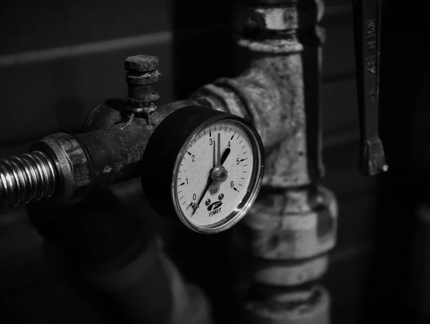
The performance acceptance test defines what "commissioned" means in measurable terms. Without it, the handover package is an opinion; with it, the package is an audit-defensible record.
Run a 7-day composite sampling campaign at design flow and compare COD, color, and TOC against the pre-commissioned influent baseline, using the same composite-sampling structure EPA 832-F-00-013 codifies for biological plants. Document the oxidant dose per kilogram of COD removed for every operating day; the engineering-recommended band is 0.5–2.0 kg H2O2 per kg COD removed, with values above 2.0 kg/kg signalling radical scavenging that the operator must investigate rather than ignore. Reconcile oxidant consumption against measured removal using the stoichiometric relationship: 1 mole of H2O2 delivers 0.5 mole of •OH, so a consumption ratio outside that band is either a measurement error or a scavenger load that has to be characterised.
The handover package should include as-built drawings, calibration certificates, the cold and hot commissioning reports, the 7-day composite data, and a written 90-day optimisation plan tied to the operating-cost target — the same structure used for biological plants, applied to AOP chemistry. For textile and dye-house applications where the AOP is replacing a legacy ozone system, the ozone oxidation cost and engineering guide for textile and dye-house AOP applications gives the unit-cost baselines the optimisation plan should be measured against. The AOP polish step also increases sludge volume; the filter-press retrofit guide for the increased sludge volume from a new AOP polish step covers the dewatering side of that consequence.
Common AOP Commissioning Failures and How to Prevent Them
Four failure modes account for the majority of AOP commissioning underperformance in industrial service. Engineer them out before the skid is energised.
Radical scavenging by alkalinity. When feed alkalinity is above 200 mg/L as CaCO3, dose-reduction alone will not restore performance — carbonate and bicarbonate anions consume •OH faster than the target organics do. A softening step or a pH-depression stage upstream of the AOP is the engineered fix; documenting influent alkalinity in the pre-commissioning baseline is what tells you whether the fix is needed. Catalyst poisoning. Fenton iron and heterogeneous catalytic AOP reactors fail when the feed carries chelating agents (EDTA, citrate) or phosphate, which complex the active sites. Map the upstream chemistry before the skid is sized; a jar test for phosphate and a screening for chelants takes a day and prevents a six-month underperformance story. UV lamp fouling. Hard-water feeds scale the quartz sleeve within weeks when Ca²⁺ exceeds 120 mg/L; specify wiper-equipped reactors or a softened feed, and inspect the sleeves during the 7-day performance test rather than at the 90-day review. Residual H2O2 carryover. A missed quench step pushes residual H2O2 into the receiving stream and inflates downstream BOD/COD, producing the same kind of post-handover compliance surprise a poorly stabilised biological plant produces — except in this case the cause is chemistry, not biology. A residual H2O2 analyser on the discharge line with a trip setpoint at 0.5 mg/L is the only reliable defence.
Frequently Asked Questions
How is the H2O2 dose selected for an AOP reactor during commissioning?
Start from the stoichiometric demand — 0.5 mole of •OH per mole of H2O2 — and validate against a bench-scale jar test on the actual influent. The engineering-recommended operating band is 0.5–2.0 kg H2O2 per kg COD removed; values above 2.0 kg/kg indicate radical scavenging by alkalinity or chloride rather than an oxidant demand problem. Confirm the dose with a pCBA probe-compound test before signing off hot commissioning.
What is the residual H2O2 target before discharge, and how is it achieved?
Residual H2O2 must be ≤ 0.5 mg/L on the discharge line, both to protect downstream biology and to avoid inflating receiving-stream BOD/COD. The target is typically met with a downstream catalytic polisher, an activated-carbon contactor, or a controlled dose of sodium bisulfite. A continuous residual H2O2 analyser with a trip setpoint is the only reliable way to gate the step; grab samples miss the transient peaks that cause the compliance failure.
How long does a typical AOP commissioning take from skid arrival to performance sign-off?
Plan on 4–6 weeks total: 1 week for site readiness and mechanical installation, 1 week for cold commissioning, 1–2 weeks for the hot-commissioning dose ramp and •OH CT validation, and 7 days for the performance acceptance test. Sites with upstream instability, high feed alkalinity, or strict effluent permits should add a buffer week for the dose-response characterisation before the 7-day composite test begins.
Which safety interlocks must be proven before the oxidant is introduced?
Four interlocks are non-negotiable: the UV lamp enclosure interlock (no lamp energisation with the housing open), the ozone off-gas destruction unit proven to hold stack concentration ≤ 0.1 ppmv, the H2O2 storage temperature interlock set to alarm at 25 °C and trip at 30 °C, and the LEL detector covering any H2-vented area. All four must appear as named rows on the cold-commissioning checklist with a date and a signature before hot work begins.
What is the role of an on-site oxidant generator in the AOP polish step?
An on-site generator — such as a on-site oxidant generator for the AOP polish or quench step — eliminates the logistics, storage, and concentration-drift problems that come with delivered oxidant chemicals. It is particularly useful for the polish step where a small, controllable oxidant dose is required to break residual H2O2 or to provide a finishing disinfection hit, and it removes the largest single handling hazard from the AOP footprint.