What UV Disinfection System Installation Delivers
UV disinfection system installation and commissioning uses one sequence: confirm post-clarifier UVT and TSS, set reactor and weirs, install sleeves and lamps, then prove dose and fecal coliform log reduction. Municipal secondary effluent typically needs UVT ≥65% at 254 nm and 30–40 mJ/cm² RED before acceptance. Startup strikes lamps; commissioning verifies dose and microbiology.
A UV train uses four engineered parts. The set is a low-pressure or medium-pressure UV lamp, a quartz sleeve that transmits 254 nm light, a reactor that sets retention time, and a ballast that regulates lamp current. The sleeve isolates the lamp from water, and UV damages microbial DNA and RNA so cells cannot reproduce. Because UV leaves no residual disinfectant, it is the last barrier before discharge.
Upstream BOD, TSS, and turbidity removal must already meet design targets, or dose shortfalls appear at startup. Commissioning verifies the installed bank delivers design UV dose — typically 30–40 mJ/cm² for municipal secondary effluent — plus design retention time and log reduction. Startup only proves lamps strike and ballasts ramp. A lamp-on event is not a pass; a validated fecal coliform log-reduction result is.
Most plants we size for open-channel UV run at the lower end of the 30–40 mJ/cm² band when post-clarifier UVT stays above 65% at 254 nm. Plants that swapped chlorine for UV, such as Florence, OR on Siuslaw River effluent in 1999, still depend on that upstream clarity. Without it, extra lamps do not recover dose.
Phase 1 — Pre-Installation Site Readiness and Water-Quality Verification
Most UV commissioning failures start in civil and water-quality work finished before the manufacturer crew arrives. The Florence, OR project log records excavation, dewatering, rebar, and about 12 yd³ and 22 yd³ concrete pours for new UV channel walls. Slide gate installation and cable routing along the new catwalk followed. Each item is a hold point for the UV manufacturer, and incomplete work slips the startup window.
Before lamps ship, the contractor checks channel dimensions against the reactor drawing, slide gate elevations, weir setpoints, cable tray routing, and safety railing around the effluent channel. Contractor scope ends at the catwalk terminal. Lamp, sleeve, ballast assembly, and energized startup stay with the manufacturer. That handoff cuts finger-pointing across the 8–12 week gap between civil completion and the manufacturer site visit (Florence project log, 2025).
Water quality must be measured before reactor selection. UVT is read with a bench spectrophotometer at 254 nm on a sample after final clarification or filtration. Municipal secondary effluent typically reads ≥65% UVT. Values below about 55% will not deliver 30 mJ/cm² at practical lamp spacing.
Dissolved organics, suspended solids, color, and UV-absorbing metals (iron, manganese) drive UVT down. Upstream TSS should stay ≤30 mg/L and turbidity ≤5 NTU for reliable dose delivery. Plants with marginal influent need stronger pretreatment screening. A rotary mechanical bar screen cuts particulates that foul quartz sleeves within days of startup.
Where oil and grease still load the clarifier, a dissolved air flotation system can hold TSS and turbidity inside the UV acceptance band before the channel is flooded.
| Pre-Installation Check | Acceptance Criterion | Owner |
|---|---|---|
| Channel dimensions vs. reactor drawing | ±10 mm tolerance, level verified | Civil contractor |
| Slide gate installation | Fasteners torqued, gates tested dry | Civil contractor |
| Weir elevation | Matches hydraulic profile (±5 mm) | Civil contractor |
| Cable routing / catwalk | Pull boxes terminated, conduit sealed | Electrical contractor |
| Safety railing | OSHA-compliant around channel | Civil contractor |
| UVT at 254 nm (post-clarifier) | ≥65% municipal, ≥75% reuse | Process engineer |
| TSS / turbidity upstream | TSS ≤30 mg/L, NTU ≤5 | Process engineer |
| Lamp / sleeve / ballast assembly | Manufacturer scope | UV manufacturer |
Phase 2 — Mechanical and Electrical Installation
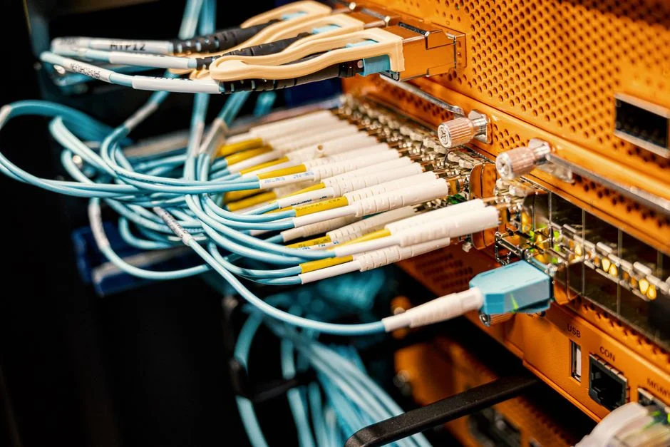
Placement sets the hydraulic baseline for open-channel parallel-lamp reactors — the type Florence installed, with lamps parallel to flow and weirs controlling water level. Set the reactor on its mounting brackets, verify lamp modules sit level, and confirm weir plates are at design elevation before any lamp is energized. A 5 mm weir error produces measurable dose maldistribution across the channel width.
Quartz sleeves are the most damage-prone part on site. Inspect each sleeve for cracks and chips before install, clean with isopropyl alcohol and a lint-free wipe (never abrasive pads), and check O-rings for compression set or cuts. Torque sleeve compression fittings to the manufacturer value — typically 8–12 N·m for 1" sleeve nuts — to avoid leaks and over-torque fracture. Do not flood the channel until every sleeve passes a dry-fit check.
Lamp installation follows sleeve verification. Seat each lamp until connector pins fully engage, then verify lamp strike on the ballast before the channel is filled. That sequence prevents a flooded channel with unproven lamps — the worst rework case. Low-pressure lamp service life runs 8,000–12,000 hours; record the install date on each module for the plant replacement schedule.
Ballast and panel mounting must meet the IP rating for the effluent channel — typically IP65 indoors and IP66 for partially exposed installs. Route control cables along the catwalk (Florence halted electrical work until catwalks were in), separate low-voltage signal from lamp power, and ground per the panel schematic. Door-interlock switches, level sensors, and UV intensity sensors must be wired and bench-tested before energizing. Those interlocks protect operators from UV exposure and protect lamps from dry running.
Compact plants that feed UV from a packaged train, such as a WSZ underground integrated sewage treatment plant, still need the same channel level, weir, and UVT checks. Packaging does not skip dose math.
Phase 3 — Commissioning: Dose Verification and Performance Acceptance
Commissioning is the engineered proof that the installed system hits design intent. Manufacturer startup — energizing lamps, setting ballast output, walking the HMI through sequences — comes first. Commissioning sits on top of that startup and uses four measurable tests, not a single checklist tick.
1. Hydraulic test. With the channel at design flow, measure flow distribution across the width with a multipoint velocity probe or dye-trace. Confirm the weir holds design water level and that calculated retention time matches the design basis. A 10% retention-time deviation is the usual pass/fail threshold.
2. Lamp intensity test. Using a calibrated UV intensity sensor at the manufacturer reference point, compare the new-lamp reading to the lamp data-sheet baseline. A reading within 90% of baseline confirms lamps and ballasts are matched. That intensity value feeds dose verification; a weak reading here will not be rescued later.
3. Dose calculation. UV dose (mJ/cm²) equals average intensity × hydraulic retention time, corrected for measured UVT, and the reduction equivalent dose (RED) is compared to the design target. For municipal secondary effluent, design dose is 30–40 mJ/cm² for 3-log fecal coliform reduction; reuse applications more often use 40–60 mJ/cm². Document UVT, intensity, and retention time with the calculation.
4. Microbiological validation. This is the acceptance test the contract signs against. Pull fecal coliform samples upstream and downstream of the UV bank across a representative flow range. Log reduction is log₁₀(influent) − log₁₀(effluent), and high residual counts flag upstream treatment as well as UV hardware, per the indicator-organism framework documented by Florence (2025).
Alarm and interlock matrix. Force and observe each alarm during commissioning, then sign it off:
| Alarm / Interlock | Forcing Method | Pass Criterion |
|---|---|---|
| High lamp temperature | Block cooling air, simulate | Alarm at setpoint, lamp shutdown |
| Low UV intensity | Disconnect reference sensor | Alarm at threshold, optional lamp bank trip |
| Lamp failure | Remove one lamp from bank | Alarm identifies failed lamp position |
| Low channel level | Drain to test setpoint | Alarm, lamps de-energize |
| Door interlock | Open panel during operation | Immediate lamp shutdown, no restart on close |
| SCADA / PLC handshake | Simulate loss of comms | Alarm logged, no false trip — see SCADA vs PLC comparison for control architecture |
Manufacturer on-site startup usually lands 8–12 weeks after civil completion. Substantial completion and microbiological acceptance follow within about 30 days of startup — consistent with Florence late-June startup and August 15 substantial completion.
Where residual chemical disinfection is still required after UV, size against a Chlorine Dioxide (ClO₂) Generator for Water Disinfection. Do not assume one barrier covers every permit limit when comparing UV with oxidant trains. For a side-by-side process view, use the ClO2 vs UV comparison guide.
Common Commissioning Failures and How to Diagnose Them
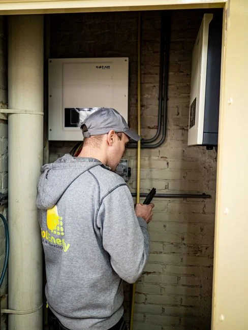
Fecal coliform still high after the UV bank. Check UVT first — it is the most common cause of dose shortfall and the cheapest measurement. If UVT is on spec, inspect quartz sleeves for fouling (wipe and re-test intensity), then check lamp age against the 8,000–12,000 hour service life.
Lamp not striking. Verify ballast output voltage at the lamp connector, check pin alignment and continuity, and confirm lamp age. A lamp near end-of-life fails to strike reliably even on a healthy ballast.
Uneven dose across channel width. Hydraulic maldistribution is the usual cause. Re-check weir setpoints and look for obstructions or air pockets. Dye-tracing at design flow shows whether the fault sits at the inlet distributor or downstream of the lamp modules.
Sleeve fouling within days of startup. Either upstream TSS is too high, or iron/manganese is precipitating on the sleeve. Sample upstream for Fe/Mn and re-evaluate pretreatment. This is rarely a UV hardware defect.
Selection Checklist and Next Step
Use this checklist before you sign substantial completion:
- Post-clarifier UVT ≥65% at 254 nm (municipal) or ≥75% (reuse), with TSS ≤30 mg/L and turbidity ≤5 NTU.
- Channel, weir, and slide-gate elevations within ±5–10 mm of the reactor drawing.
- Every quartz sleeve dry-fit, cleaned, and torqued to 8–12 N·m (or manufacturer value).
- New-lamp intensity ≥90% of data-sheet baseline at the reference sensor point.
- Calculated RED within design (30–40 mJ/cm² municipal; 40–60 mJ/cm² reuse) using measured UVT and retention time.
- All alarms forced and signed off, including low level, door interlock, and lamp failure.
- Upstream/downstream fecal coliform log reduction documented across the design flow range.
Who this is for: plant engineers, EPC contractors, and procurement managers buying or accepting open-channel or vessel UV banks on municipal or industrial secondary effluent. Who should look elsewhere: sites that still need a persistent residual for distribution, or that cannot hold UVT above ~55% without major pretreatment. Those cases often need a chemical barrier such as a Chlorine Dioxide (ClO₂) Generator for Water Disinfection in series or instead. Next step: send channel drawings, UVT data, and target log reduction with your UV installation and commissioning inquiry so dose and lamp count can be checked against the hydraulic profile.
Frequently Asked Questions
What UVT is required before a UV disinfection system can be commissioned?
Municipal secondary effluent typically requires UVT ≥65% measured at 254 nm on a bench spectrophotometer, with TSS ≤30 mg/L and turbidity ≤5 NTU. Values below about 55% UVT will not deliver 30 mJ/cm² at any practical lamp spacing, regardless of reactor size (per standard UV design basis, 2025). Reuse trains usually target ≥75% UVT before dose acceptance.
What UV dose is needed for 3-log fecal coliform reduction?
A reduction equivalent dose of 30–40 mJ/cm² at the design UVT and retention time achieves 3-log fecal coliform reduction for municipal secondary effluent. Reuse applications typically require 40–60 mJ/cm². The dose must be calculated from measured intensity, retention time, and UVT, not assumed from lamp count alone.
How long does UV system commissioning take after civil work is complete?
Manufacturer on-site startup typically occurs 8–12 weeks after civil completion, with substantial completion and microbiological performance acceptance within about 30 days of startup. The Florence, OR UV project documented late-June startup and August 15 substantial completion (Florence WWTP project log, 2025), which matches the industry-typical 8–12 week gap.
What is the difference between UV startup and UV commissioning?
Startup is the manufacturer energizing sequence — lamps strike, ballasts ramp, and the HMI powers up. Commissioning is engineered verification of dose delivery (mJ/cm²), hydraulic retention time, and microbiological log reduction against the design basis. A lamp-on event is not a commissioning pass; a fecal coliform log-reduction result is (per Florence WWTP project documentation, 2025).