

How a Disc Filter Works in Tertiary Polishing
How a disc filter works: secondary effluent flows inside-out through stacked discs with 10–60 µm polyester mesh; cake raises capture until filtrate spray backwash clears the mesh without stopping filtration. An 18 µm Hydrotech HF2220 at Billund cut particle count 89.7% and mass 75.6%, with effluent SS at 3–8 mg/L from about 20 mg/L feed (Simon et al., Water, 2019).
Plant engineers specify these units when UV, RO, or reuse limits need stable low solids after clarification. Most municipal trains place the filter after secondary clarification and ahead of disinfection or membranes, not as a clarifier substitute.
Inside the Disc: How Solids Are Actually Captured
Disc filters capture solids through a two-stage mechanism that product pages rarely decompose into operating physics.
Stage 1 — direct interception. Particles larger than the mesh aperture are sieved on the inner disc surface. This is the rated capture and matches the nominal pore size on the data sheet. For an 18 µm mesh, particles above 18 µm stop at the woven filaments.
Stage 2 — cake filtration. As solids accumulate, the deposit itself becomes a finer filter and traps sub-mesh particles that would otherwise pass. The 2019 Billund study attributes part of its 75.6% mass removal to this cake-mediated capture. The cake progressively improves retention beyond bare mesh alone. More dirt produces better filtration until head loss forces a backwash cycle.
The same authors observed many microplastic particles larger than the pore size in the filtrate. They read that as cake capture plus some bypass. Field performance often beats the printed pore size because of cake, but the barrier is not absolute.
Submergence is the second physical lever. On a HUBER RoDisc, up to 65% of disc area sits below the waterline at any instant (HUBER product documentation). That submerged fraction is the effective filter area and the denominator in hydraulic loading. Discs rotate only during backwash on HUBER designs, so cake builds on a stationary mesh until the ΔP setpoint starts cleaning.
How Does the Reverse Wash Mechanism Work?

Disc filter reverse wash is a ΔP-triggered spray of filtrate from outside the mesh that removes cake without stopping forward filtration. As cake builds, head loss across the mesh rises. Because the HUBER RoDisc is a gravity-flow system with a fixed overflow weir, upstream tank level climbs with pressure differential. When level hits the setpoint — typically a ΔP in the 30–50 kPa range for tertiary polishing — the controller starts a backwash event.
On a HUBER-style unit, the shaft begins slow rotation and a spray bar fires filtrate at the mesh from the outside, dislodging cake. Wash water plus solids fall into a collection trough and leave axially. On continuous-rotation designs, only a 5–15% segment of disc area is offline at once. That segment is cleaned for 30–120 seconds before returning to service. Upstream flow is not interrupted. Available filter area drops about 5–10% during the cleaning window.
The wash medium is filtrate, not fresh water. That reuse underpins the 95–98% recovery figure commonly quoted for tertiary polishing. HUBER states that no external wash-water supply is required because filtrate cleans the mesh. Periodic chemical cleaning (CIP) is still needed for biofouling or scale that spray alone cannot remove. Intervals are typically monthly to quarterly on tertiary municipal duty, and shorter on industrial feeds with high scaling potential.
Where a Disc Filter Sits in the Treatment Train
A disc filter is a polishing device, not a primary clarifier. It assumes upstream processes already removed bulk solids, organics, and oil or grease.
The canonical municipal train is: primary sedimentation → activated sludge → secondary clarification → disc filter → UV or RO. At Billund WWTP in the 2019 study, secondary clarifier effluent carried about 20 mg/L SS. The disc filter reduced that to 3–8 mg/L before discharge. The unit sits between biology and disinfection or membranes. Both downstream steps are sensitive to particles: UV transmittance falls sharply above about 10 mg/L SS, and RO membranes foul when silt density index (SDI₁₅) exceeds 3–5.
Where oil, grease, or high TSS is present in the feed, a DAF system for upstream FOG and TSS reduction is typically specified ahead of the disc filter. That limits premature mesh blinding and reject spikes from FOG breakthrough. Compact plants that combine clarification and polishing in one skid sometimes evaluate an Integrated Water Purification System (JY Series) before adding a dedicated disc stage. HUBER lists two non-negotiable pre-treatment rules: a 3 mm rotary bar screen for pre-screening and zero oil or grease in the feed. Failure on either condition causes blinding, spray-bar fouling, and missed effluent targets regardless of disc count.
Downstream benefits are concrete. UV needs low SS for transmission, typically below 10 mg/L. RO needs low SDI, which 40–60 µm meshes often support as pretreatment. The Billund numbers remain the cleanest published proof for this train position: 89.7% particle-count removal, 75.6% mass removal, and effluent SS of 3–8 mg/L from a 20 mg/L feed.
| Process Node | Typical Influent SS | Typical Effluent SS | Function |
|---|---|---|---|
| Primary sedimentation | 200–400 mg/L | 100–200 mg/L | Bulk settleable solids |
| Activated sludge + secondary clarifier | 100–200 mg/L | ~20 mg/L | Biological oxidation + clarification |
| DAF (if FOG present) | 100–500 mg/L | 20–50 mg/L | Oil/grease + floatable solids |
| Disc filter (18 µm reference) | ~20 mg/L | 3–8 mg/L | Tertiary polishing, microplastic capture (per MDPI 2019) |
| UV / RO | 3–8 mg/L | Disinfected or desalted | Disinfection or membrane barrier |
Mesh Pore Size: 10 vs 18 vs 40–60 µm and When to Specify Each
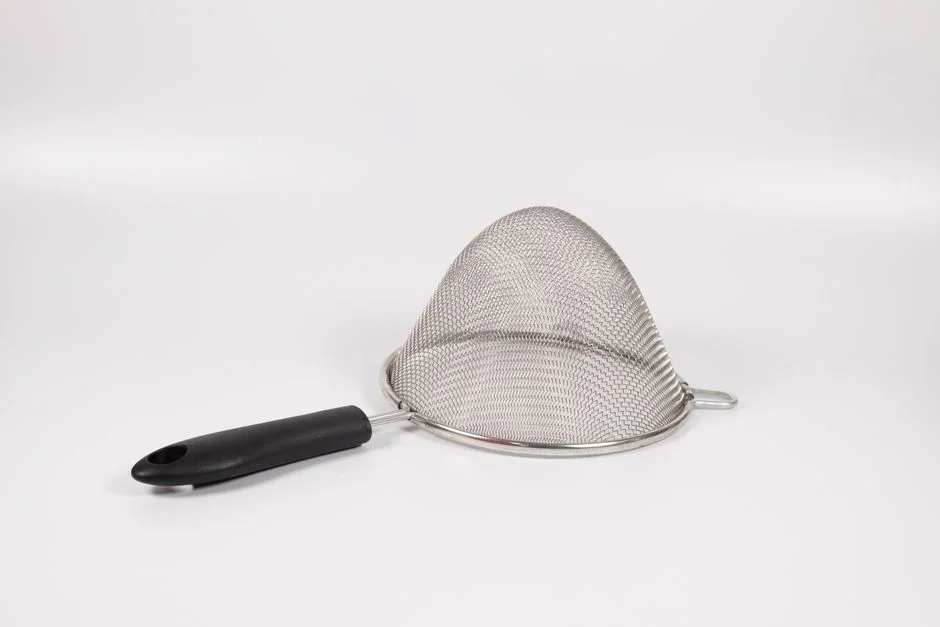
Mesh aperture is the single specification that most directly drives both capital cost and operating cost on tertiary disc duty.
10 µm is the performance ceiling. HUBER offers it as the finest standard mesh. It delivers the lowest effluent SS and the highest TSS removal, but it blinds fastest, demands the most frequent backwash, and produces the highest reject volume and spray-pump duty. Specify 10 µm only when reuse limits or a high-fouling RO feed genuinely cannot tolerate higher SS.
15–18 µm is the standard for tertiary reuse and microplastic capture. The 2019 Billund study used 18 µm and recorded 89.7% particle-count removal, 75.6% mass removal, and 3–8 mg/L effluent SS. This aperture is the default for municipal polishing where the goal is reliable SS reduction without the backwash penalty of 10 µm. Plants fighting downstream membrane fouling often find 18 µm solves the problem without the reject cost of 10 µm.
40–60 µm is the pre-RO polishing standard when the objective is SDI reduction and gross solids removal, not absolute TSS. Coarser mesh extends backwash intervals and cuts reject volume, which is why it dominates seawater and brackish RO pretreatment. The trade-off rule we use in proposals: every roughly halved pore size roughly doubles backwash load. Present that to clients as reject volume in m³/day rather than as a vague percentage.
| Mesh Aperture | Typical Use Case | Effluent SS (Reference) | Reject Volume | Backwash Frequency |
|---|---|---|---|---|
| 10 µm | Strict reuse limits, high-fouling RO feed | < 3 mg/L | Highest (baseline × ~2) | Highest |
| 15–18 µm | Tertiary reuse, microplastic capture | 3–8 mg/L (per MDPI 2019) | Moderate (baseline) | Moderate |
| 40–60 µm | Pre-RO SDI reduction, seawater RO pretreatment | 5–15 mg/L | Lowest | Lowest |
Sizing a Disc Filter: Discs, Submergence, and Hydraulic Loading
Disc filter sizing starts from a published hydraulic benchmark, then scales disc count against design flow, mesh, and submergence. Understanding how a disc filter works at scale means treating disc count as effective area, not as a catalog ornament.
The Hydrotech HF2220 reference unit handles 1200 m³/h across 13 discs at 18 µm with about 65% submergence (Billund WWTP context, 2019 study). For a design flow of 800 m³/h at the same 18 µm aperture, linear scaling gives about 9 discs (800/1200 × 13 = 8.7, rounded up to 9). That count is only a starting estimate. The OEM must confirm disc diameter, spacing, and submergence geometry.
The general hydraulic loading formula is: design flow ÷ (number of discs × disc area × submergence factor). On a HUBER RoDisc, submergence is fixed at up to 65%. On a partially submerged drum, submergence varies with rotor position and must be integrated over the rotation cycle. A HUBER RoDisc shaft can carry up to 35 discs, so a 9-disc duty fits in a single-shaft envelope and leaves room for expansion. Most plants we size for 500–1000 m³/h tertiary duty land in the lower half of that shaft capacity so spare discs can be added later.
Reject water is the second sizing output. With recovery in the 95–98% range, reject is 2–5% of throughput. At 800 m³/h continuous duty, 2% reject equals 16 m³/h (384 m³/day). At 5% reject the figure is 40 m³/h (960 m³/day). Oil-bearing waste pushes the higher end. When routing reject back to headworks creates a solids recycle loop, a filter press selection for the reject stream is often the next decision.
OEM confirmation is mandatory before procurement. Disc diameter, spacing, and submergence fraction vary by vendor. Nine discs on one platform may not match nine on another. Flows above a single shaft’s capacity should use parallel trains rather than oversized shafts, because access and redundancy both favor modular units.
Selection Checklist and Cost Drivers
Disc filter selection for tertiary polishing should clear these checks before a purchase order:
- Influent SS after secondary clarification typically ≤ 20–30 mg/L for tertiary mesh duty
- Mesh aperture matched to goal: 10 µm for strict reuse, 15–18 µm for tertiary SS/microplastics, 40–60 µm for pre-RO SDI
- 3 mm pre-screen installed and FOG confirmed absent in the feed
- Reject handling sized for 2–5% of throughput at continuous design flow
- CIP interval planned for biofouling or scale on the selected wastewater
- Spare disc capacity or parallel train for peak wet-weather or future flow
- Downstream UV/RO SDI or SS limit written into the performance guarantee
Main cost drivers are mesh fineness (backwash energy and reject volume), disc count and tank civil works, spray-pump duty, and CIP chemistry — not the filter media alone.
Who This Is For / Next Step
This mechanism guide is for plant engineers, EPC process leads, and procurement teams specifying tertiary polishing ahead of UV, RO, or reuse discharge. Teams still fighting primary FOG or unsettled secondary sludge should fix upstream clarification first. A disc filter will not replace that work. If you need a duty-specific mesh and disc count for your flow and effluent limit, send the influent SS, design m³/h, and downstream barrier type via our request a disc filter sizing quote form.
Frequently Asked Questions
What mesh size should I specify for pre-RO disc filtration?
For pre-RO polishing aimed at SDI reduction rather than absolute TSS removal, 40–60 µm is the usual choice because it lengthens backwash intervals and cuts reject volume. The 2019 Billund study used 18 µm for tertiary reuse and microplastic capture and reported 3–8 mg/L effluent SS. Reserve 10 µm for reuse limits or high-fouling RO feeds where the extra reject cost is justified by the solids target.
How much reject water does a disc filter produce?
Tertiary polishing recovery typically exceeds 95%, so reject is about 2–5% of throughput. At 800 m³/h design flow that is 16–40 m³/h, or 384–960 m³/day at continuous duty. Every roughly halved mesh pore size roughly doubles backwash load, so 10 µm sits at the upper end of reject volume while 40–60 µm sits at the lower end under the same solids load.
How often does a disc filter backwash and how much water does it use?
Backwash starts when differential pressure or upstream level hits the controller setpoint, often corresponding to about 30–50 kPa on tertiary gravity units or roughly 150–300 mm head loss on level-based controls. Under normal municipal solids loading, wash water is filtrate and usually stays within about 0.5–5% of plant flow depending on mesh and influent SS. Continuous-rotation designs keep most disc area online during the 30–120 second clean of each segment.
Can a disc filter replace a secondary clarifier?
No. Disc filters remove suspended solids as tertiary or polishing units and do not provide the biological solids inventory or sludge settleability control of a secondary clarifier. They assume upstream biology and clarification already did bulk solids work. Pairing with MBR or IFAS can shrink downstream clarification footprint, but the disc stage still does not replace secondary clarification biology.
How does a disc filter work in wastewater treatment?
A disc filter utilizes a series of vertically mounted, circular filter discs covered in fine filter media, typically polyester or stainless steel mesh. As influent wastewater flows into the center drum and passes outward through the media, suspended solids are captured on the internal surfaces. As the solids build up, the head loss increases, triggering a rotation of the discs and the activation of backwash spray nozzles that remove the accumulated cake, which is then diverted to a waste trough.
What suspended solids level can a disc filter achieve?
On well-run tertiary municipal duty, an 18 µm reference train reduced SS from about 20 mg/L to 3–8 mg/L in the Billund data set. Optimized plants with finer mesh and stable upstream biology can target below 5 mg/L, and some high-performance duties report 1–2 mg/L. Results still track influent particle size distribution and secondary process stability more than nameplate pore size alone.