
What 'Commissioning' Actually Means for an Electrocoagulation System
Electrocoagulation system installation and commissioning is a staged, gated protocol — not a single "turn it on" event on the day the truck arrives. The four gates are factory acceptance test (FAT), site acceptance test (SAT), mechanical/electrical/instrumentation completion (MEIC), and performance guarantee test (PGT). Each gate produces a signed document; the next cannot start until the previous is countersigned. This sequencing follows the design → install → commission pattern that BSI-style process-equipment standards use as a structural template (per BSI 15287, 2026) — the chimney standard is cited here only for the workflow shape, which transfers cleanly to any process skid including an electrocoagulation reactor.
EC commissioning diverges from chemical coagulation commissioning in two ways. First, there is no chemical dosing skid to commission — the "coagulant" is generated in situ by sacrificial Al or Fe anodes under low-voltage DC, so the critical path shifts to rectifier calibration, electrode alignment, and polarity-reversal logic. Second, the system cannot be meaningfully benchmarked on clean water alone; the electrode surface chemistry, the conductivity window, and the floc/foam separation all depend on real wastewater. Most plant failures trace back to a contractor who signed SAT on a clean-water run and then discovered the PGT failed because conductivity was 600 µS/cm instead of the assumed 2,500 µS/cm (HydropureWater field data, 2026). Treat the clean-water and process-commissioning phases as separate gates, with separate sign-off paperwork.
Pre-Installation: Engineering Documents and Site Readiness
Seven documents must be on the engineer's desk two weeks before the reactor ships: P&ID, GA drawing, electrical single-line diagram, electrode layout drawing (with plate count, plate area, and gap dimension), O&M manual, spare-electrode list, and the FAT report. If any of these are missing, hold the shipment — fixing a dimension error on the shop floor takes an afternoon; fixing it after the reactor is grouted takes a month.
Site readiness is the most common cause of commissioning delay. The reinforced concrete plinth must be sized for the reactor's full operating weight with water (not just dry weight — a 5 m³ EC cell gains roughly 5 tonnes when filled). Provide at least 1 m of clear access on two sides for electrode rack removal during plate changes. Floor coating should be acid-proof epoxy or vinyl ester with a bunded lip rated for 110% of the reactor volume, because electrolyte carryover and acid-cleaning operations will eventually contact the floor. The feed pump must be sized to the design flow at the actual suction conditions, and an upstream bar screen with ≤2 mm aperture is non-negotiable — rags and fibres wrapped across an electrode gap will arc, pit the plate edge, and trip the rectifier within hours.
Utility prerequisites include three-phase power at the rectifier's full kVA rating (not the running rating — inrush on a thyristor-controlled rectifier can be 2–3× running current), an inlet screen, a sludge withdrawal sump at the reactor outlet, and an on-site conductivity measurement of the influent. If influent conductivity is below ~1,000 µS/cm, plan an electrolyte dosing point or a pre-salt injection — DC current cannot be carried by pure water, and the rectifier will current-limit well below the design current density if conductivity is marginal.
Mechanical Installation: Reactor, Electrodes, and Hydraulics
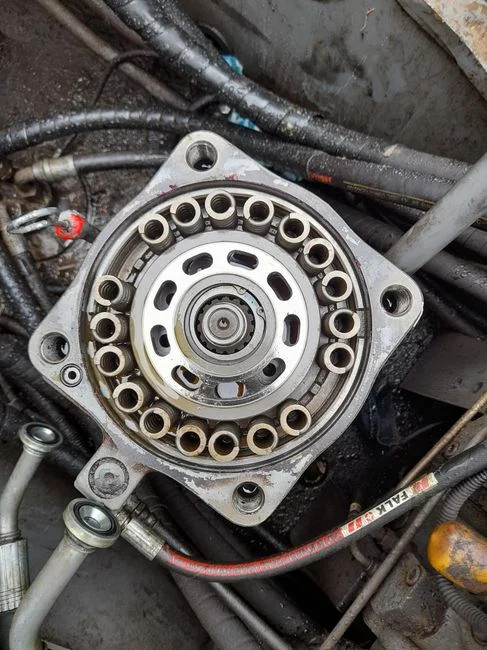
Mechanical installation of a skid-mounted EC unit is a 2–4 day activity, as most units arrive on a single frame with the electrode rack pre-spaced. The sequence matters more than the speed. Step 1: set the reactor on the plinth, shim to a level of ≤2 mm/m across the long axis, and dry-align the inlet/outlet flanges to the connecting pipework before any anchor bolts are grouted. Grouting first and aligning later is the most common cause of stress cracks in the electrode-support frame. Step 2: install the electrode plates one bank at a time, and verify the inter-electrode gap with feeler gauges at the top, middle, and bottom of every plate. The target is 3–10 mm; uneven spacing creates dead zones (low current density, no floc generation) and accelerated plate wear on the tight-gap side.
Step 3: connect the inlet distributor, outlet weir, and sludge hopper. Confirm gravity fall to the sludge sump or to the downstream dewatering unit — the hopper should have a slope of at least 60° to prevent sludge bridging on Fe-saturated floc. Step 4: install the DAF system for downstream floc separation immediately after the reactor if the design uses EC + flotation. The interface piping should be as short as practical (typically <3 m) because the EC-generated H₂ micro-bubbles are the carrier gas for the floc; let them collapse and you lose the flotation effect. Mechanical completion is documented on the MC checklist before any electrical work begins.
Electrical and Electrode Setup: Rectifier, Polarity, and PLC
Electrical setup is the most failure-prone part of an EC install. The DC rectifier is sized as follows: voltage window typically 6–30 V DC (most cells run 8–18 V), and current sized to total electrode area at the design current density. Current density for industrial EC reactors sits in the 10–150 A/m² range depending on wastewater conductivity and target contaminant (EC literature, per Condorchem, 2025). For a 2 m² total anode area at 80 A/m² you need a 160 A rectifier, not the 100 A unit a sales quote sometimes includes.
Polarity reversal is a required commissioning step. Wire the rectifier for automatic reversal with a PLC timer set to 5–20 minutes per half-cycle. The reversal dissolves the calcium and oxide scale that builds up on the cathode; without it, the cathode passivates within hours on hard-water feeds and the cell voltage climbs until the rectifier trips. Confirm the PLC logic before energizing: reversal should pause current for roughly 1–2 seconds (dead time) to allow the surface layer to equilibrate, then resume at the opposite polarity.
Instrument loops to commission include the rectifier voltmeter and ammeter (calibrated against a clamp-on reference), pH probe on inlet and outlet, conductivity probe on inlet, temperature probe in the cell, and tank level switches for the feed and sludge compartments. Safety items per current 2026 IEC/UL wiring practice: emergency stop at the rectifier within 1.5 m of the operator position, DC-side lockable isolator, IP65 junction boxes within 1 m of the reactor, and a clearly labelled grounding electrode bonded to the reactor frame and the rectifier chassis. An automatic chemical dosing system is only required when influent conductivity cannot support the design current density — for most dyeing, metal-finishing, and F&B wastewaters it is not needed.
Water Commissioning: From Clean Water to Real Wastewater
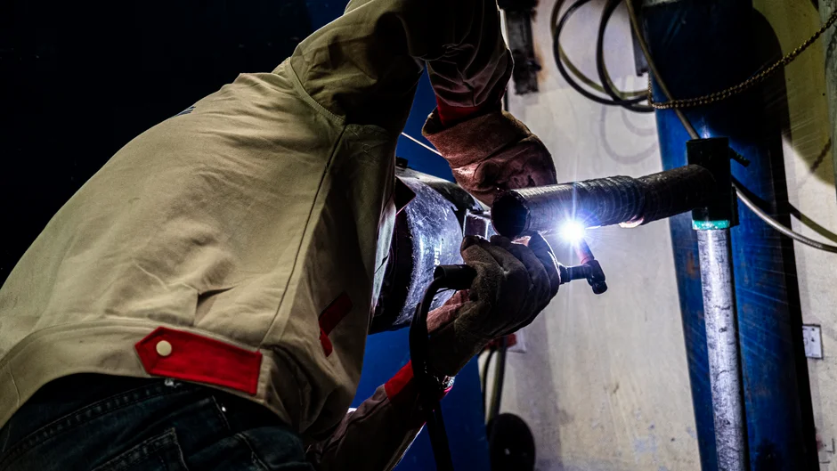
Water commissioning consists of two distinct phases. Phase 1 (clean water run): fill the reactor with tap or clarified water, energize the rectifier at 30% of rated current, and walk the length of the electrode rack. Bubble distribution should be visibly even across every gap — typically 1–3 mm bubble columns rising at roughly equal rate. Uneven bubbles mean a misaligned plate or a partial short. Phase 1 also verifies the hydraulics: confirm HRT within ±10% of design, no dead spots in the inlet distributor, and weir draw-off across the full outlet width.
Phase 2 (real wastewater): introduce feed and step the current density up in 25% increments, holding each step for 4–8 hours before sampling. Do not jump straight to design current density — passivation risk is highest in the first 24 hours of fresh electrode exposure, and a slow ramp builds a protective oxide layer. Sample at each step for: influent vs. effluent COD, turbidity (NTU), TSS, the target contaminant (e.g., Cr, Cu, Zn, Ni, FOG, or dye absorbance depending on the application), and pH shift across the reactor. Pass criteria template: ≥80% of design removal efficiency at design flow, with power consumption within ±10% of nameplate and no more than 0.5 unit pH drift unless otherwise specified. That pass criterion is a defensible contract clause; "the water looks clearer" is not.
Commissioning KPI Table and Handover
The handover package includes a commissioning KPI table the supplier signs against, plus three documents: the SAT report, the MEIC checklist, and the PGT certificate with measured-vs-guaranteed values. Use the parameter set below as a starting point and tailor the targets to the contract.
| Category | Parameter | Unit | Typical EC Range / Target |
|---|---|---|---|
| Electrical | Cell voltage | V DC | 6–30 (8–18 typical) |
| Electrical | Current density | A/m² | 10–150 (application-dependent) |
| Electrical | Polarity reversal interval | min | 5–20 |
| Hydraulic | Flow rate | m³/h | Per design basis |
| Hydraulic | HRT | min | 5–60 |
| Hydraulic | Recirculation ratio | — | 0–100% (if used) |
| Process | COD removal | % | 50–90 |
| Process | Turbidity (effluent) | NTU | ≤5 (or per spec) |
| Process | Target metal (Cu, Cr, Zn, Ni) | mg/L | Per discharge limit |
| Process | pH shift across reactor | units | ≤0.5 (typical) |
| Electrode | Inter-electrode gap | mm | 3–10 |
| Electrode | Expected plate life | operating hours | 2,000–8,000 (per design) |
Monitoring after handover includes weekly visual plate inspection (check for pitting, scaling, or uneven wear), monthly current-density calibration against a reference ammeter, and quarterly sludge yield check against the design basis. EC sludge is low-volume and stable compared with chemical-coagulation sludge, so a filter press for the EC sludge stream can be sized conservatively — typically 30–50% smaller than the equivalent chemical-coagulation dewatering train (HydropureWater field data, 2026). For broader compliance context, cross-reference the 2026 industrial wastewater compliance guide when setting discharge limits; for retrofits of an existing dewatering line, the filter press retrofit and upgrade guide covers the typical capacity-uplift path that follows an EC install.
Frequently Asked Questions
How long does electrocoagulation reactor commissioning take from delivery to PGT sign-off?
A skid-mounted industrial EC unit typically takes 2–4 days for mechanical install, 1–2 days for electrical and PLC setup, 1 day for clean-water commissioning, and 3–5 days for stepped real-wastewater commissioning. Total elapsed time is 2–3 weeks including the 72-hour PGT run, assuming site readiness and documentation are complete on arrival.
What causes electrode passivation during commissioning, and how is it prevented?
Passivation is an insulating oxide layer (mainly calcium carbonate and metal oxide) building up on the cathode surface, which drives cell voltage up and current density down. The standard fix is automatic polarity reversal every 5–20 minutes, plus a slow current ramp during the first 24 hours of fresh electrode exposure to build a controlled protective layer.
How is current density chosen for a given wastewater?
Current density is set by the target contaminant and the influent conductivity. Heavily contaminated or low-conductivity streams (dyeing effluent, heavy-metal rinse water) need 80–150 A/m²; high-conductivity FOG or oil-field waste can run at 10–40 A/m². The rectifier is sized to the total