Why Semiconductor Fabs Near Milwaukee Need a Dedicated Pretreatment Strategy
A semiconductor fab in the MMSD service area (Milwaukee, Waukesha, Racine, and Kenosha counties) cannot discharge raw process wastewater to the sanitary sewer because the federal pretreatment program treats the fab as an Industrial User (IU) and the Milwaukee Metropolitan Sewerage District (MMSD) imposes numeric or narrative local limits on top of 40 CFR Part 403. Under 40 CFR 403.3(j), an IU is any non-domestic source that discharges to a POTW; the POTW's job is to protect its NPDES permit, its biosolids program, and its receiving waters from pass-through (40 CFR 403.3(p)) and interference (40 CFR 403.3(k)) — meaning pollutants that exit the POTW still in violation, or that disrupt the activated-sludge process itself. Semiconductor chemistry generates the exact pollutants that trigger both failure modes.
The semiconductor-specific pollutants that consistently drive local limits in 2026 are fluoride from HF, SC1 (NH4OH/H2O2/H2O) and SC2 (HCl/H2O2/H2O) etches; copper from CMP slurries and ECD plating; ammonia and TMAH from photoresist developing and stripping; plus pH excursions, TSS, and trace metals from resist stripping and brush-scrubber dumps. MMSD requires industrial users to demonstrate compliance at the point of connection to the collection system, not at the process outlet, per 40 CFR 403.5(c) (per EPA, 2025-08). That single rule is why fabs run segregated, monitored streams all the way to the sewer tap rather than a single combined equalization basin.
The Regulatory Floor: 40 CFR Part 403 and MMSD Local Limits in 2026
40 CFR Part 403 — the General Pretreatment Regulations — is the federal baseline every IU in the MMSD service area sits on. It defines prohibited discharge standards (40 CFR 403.5), categorical standards for specific industries, and the procedural rules that drive local-limit development. Most prohibited discharge standards in 40 CFR 403.5 are narrative rather than numeric, which is why each POTW, including MMSD, must derive its own local limits to protect its specific plant configuration, biosolids end-use, and receiving waters (per EPA, 2025-08).
The local-limit development rules in 40 CFR 403.5(c) require every POTW with a POTW-developed pretreatment program to identify pollutants of concern, calculate maximum allowable headworks loadings (MAHLs), set numeric or narrative limits, perform an annual review, and re-evaluate the limits periodically. Limits can be numeric effluent caps, narrative best-management practices, or both (per EPA, 2025-08). For a 2026 fab project, the practical implication is that the local-limit envelope is a moving target — engineering specifications should hold a 20–30% design margin below the current limit so the system does not become non-compliant the next time MMSD re-runs the MAHL calculation.
Three enforcement priorities are tightening across the Great Lakes region in 2026: PFAS monitoring in industrial discharges, copper (driven by both wafer-fab chemistry and WI DNR biosolids loading limits), and fluoride (driven by POTW toxicity concerns and aeration-tank foaming). A fab in the MMSD service area should expect more frequent sampling, lower method-detection limits, and a higher probability of being classified as a Significant Industrial User (SIU) once discharge volume exceeds 25,000 gpd or the pollutant load passes the SIU threshold.
Inside the Three-Stream Pretreatment Train Used by Modern Fabs
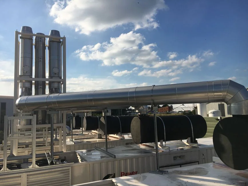
The reference treatment train, modeled on the design Samsung Austin Semiconductor describes, splits fab wastewater into three parallel streams and runs each to its own quality target before they merge at a final monitoring header. This is the same architecture most large U.S. fabs adopted after 2015 because it lets each chemistry be optimized independently and prevents a slug in one stream from knocking out the whole plant.
- Stream 1 — pH neutralization. Acidic waste (HF-bearing, SC2) and alkaline waste (SC1, TMAH-bearing) are collected in separate sumps, equalized, then dosed with NaOH or H2SO4 through PLC-controlled chemical dosing systems for pH, fluoride, and copper precipitation. An in-line pH probe verifies the 5–9 band before the stream joins the common discharge header. Anything outside band is automatically diverted back to equalization.
- Stream 2 — fluoride treatment. Calcium chloride or lime is dosed to precipitate fluoride as CaF2. The slurry passes through a lamella clarifier for solids separation, then a plate-and-frame filter press for CaF2 cake dewatering produces a 30–40% dry-solids cake. Samsung ships its CaF2 cake to a local end-user who reuses it as a feedstock in industrial wastewater treatment, eliminating landfill disposal.
- Stream 3 — copper treatment. Ion exchange resins are replacing legacy chemical co-precipitation because they eliminate sludge generation, reduce chemical use by roughly 2 million lb/yr at full scale, and shrink the system footprint by about 65% (per Samsung Austin operating data, 2020, validated as the design baseline for 2026 builds). The exhausted resin is shipped off-site for metal recovery or regeneration.
- Polishing step. A multimedia filter or MBR downstream of the three streams keeps TSS under the local cap when flows are variable, and provides a final barrier before the sewer tap.
Each stream ends with continuous online monitoring (pH, fluoride ISE, copper ion-selective electrode or UV-vis) and an automatic diversion to recycle if the quality parameter is exceeded. The diversion-and-recycle logic is what keeps the plant in compliance during a tool-side upset rather than triggering a non-compliance event.
| Stream | Unit Operation | Typical Influent | Design Effluent | Side-Stream Output |
|---|---|---|---|---|
| 1 — pH | Equalization + PLC dosing + in-line probe | pH 1–13 swings | pH 5.5–9.5 | None (gas only) |
| 2 — Fluoride | CaCl2/lime precipitation, lamella, filter press | F⁻ 100–500 mg/L | F⁻ <10–25 mg/L | CaF2 cake ~35% DS |
| 3 — Copper | Ion exchange (chelating resin) | Cu 5–50 mg/L | Cu <0.5–1 mg/L | Spent resin (off-site regen) |
| Polishing | Multimedia filter or MBR | TSS 30–150 mg/L | TSS <30 mg/L | Backwash to head of train |
Expected Local-Limit Envelope vs. Effluent Targets for Milwaukee-Area Fabs
The exact MMSD local-limit values are IU-specific and flow-dependent and must be pulled from the MMSD pretreatment program for the specific facility, but the envelope for a typical U.S. fab permit in 2026 falls inside the bands below. The fab's design effluent must sit well below the upper end of each band to absorb load growth and the annual MAHL re-evaluation that 40 CFR 403.5(c) requires (per EPA, 2025-08). Local limits may also be narrative, including BMPs, so the compliance plan has to cover both numeric caps and operating practices.
| Parameter | Typical MMSD-Style Local-Limit Envelope | Fab Design Effluent Target | Unit Operation Responsible |
|---|---|---|---|
| pH | 5.0–11.0 (standard IU range) | 6.0–9.0 | Stream 1 — neutralization + in-line probe |
| TSS | ~250–500 mg/L | <30 mg/L | Lamella clarifier + multimedia/DAF polish |
| Fluoride | ~10–50 mg/L | <10–25 mg/L | Stream 2 — CaF2 precipitation + filter press |
| Copper (total) | ~0.5–3 mg/L | <0.5–1 mg/L | Stream 3 — ion exchange |
| Ammonia (as N) | ~20–50 mg/L (site-specific) | <10 mg/L | Biological or breakpoint chlorination (if required) |
| Oil & Grease | ~50–100 mg/L | <10 mg/L | DAF or skimmer |
For a new fab in the MMSD service area, fluoride and copper are the two parameters that drive equipment sizing, chemical storage, and resin selection. pH is the parameter most likely to drive a permit violation, because tool-side dumps can swing the equalization basin in minutes; it is also the cheapest to mitigate if the dosing system is properly sized. TSS is rarely the design-limiting parameter once a lamella clarifier is installed, but it is the parameter most likely to fail a slug event when flows are variable. Sizing the downstream high-efficiency lamella clarifier for CaF2 and metal-hydroxide settling with a 1.5x hydraulic margin and pairing it with a DAF system for TSS and colloidal copper polishing covers the worst-case tool dump.
Source Reduction and Water Reclaim: Cutting Load Before Treatment
The cheapest kilogram of fluoride or copper is the one that never enters the drain. Segregation at the tool — keeping HF rinses off the brush-scrubber header, capturing CMP slurry at the tool drain rather than the floor drain — is the highest-return BMP a fab can install, and it is the lever Samsung's environmental team credits as the foundation of its compliance program. Chemical substitution (e.g., dilute-HF alternatives for some cleans, peroxide-based strippers in place of certain solvent-bearing formulations) directly reduces the fluoride and TMAH mass load on the central treatment system.
Reclaim is the second pillar. Spent UPW rinse streams are collected, monitored, polished through activated carbon plus ion exchange, and routed back to UPW makeup — Samsung reclaims about 60% of its UPW makeup this way, which directly cuts both city-water OPEX and the mass load on the pretreatment train. First-pass RO reject, which is typically 20–25% of the UPW feed, is captured by a Brine Recovery RO that recovers about 75% of the reject volume and saves roughly 90 million gallons per year of city water at a full-size fab (per Samsung Austin operating data, 2020). A brine-recovery RO to reclaim first-pass reject combined with multimedia filtration upstream of the RO is the standard reclaim package for a 2026 fab design.
For a Milwaukee-area fab, 50–70% reclaim of UPW makeup is realistic and directly cuts the fluoride, copper, and TSS mass that the pretreatment train has to handle. Source reduction and reclaim together usually shrink the central treatment system by one capital-expansion step over a 10-year production ramp.
2026 Procurement and Compliance Checklist for a New or Expanding Fab Near Milwaukee
- Pull the current MMSD local limits and SIU classification. Confirm whether categorical standards apply in addition to local limits, and identify the slug-control limits and the 24-hour composite-sampling requirements at the point of connection.
- Map each tool to one of the three streams. Define design influent ranges for pH, fluoride, copper, TSS, and TMAH. These ranges, not the local-limit envelope, drive chemistry-stage sizing.
- Specify PLC-controlled dosing, online analyzers, and automatic diversion-to-recycle on every stream. Robust automation combined with operator monitoring is the design philosophy Samsung credits for its 100%-plus compliance award run, and it is the de facto standard a Milwaukee-area fab will be benchmarked against.
- Plan sludge handling from day one. Lamella clarifier underflow goes to a plate-and-frame filter press; CaF2 cake needs a defined end-user or disposal path before the system is commissioned, not after.
- Build the self-monitoring and reporting program. 24-hour composite sampling at the point of connection, chain-of-custody, and quarterly compliance reports aligned to MMSD's annual local-limit review cycle (per EPA, 2025-08).
- Build the reclaim loop into the design. RO brine recovery and UPW rinse reclaim should be commissioned in parallel with the pretreatment train so the system ships meeting local limits on day one and keeps scaling as production grows.
Frequently Asked Questions
What regulatory framework governs semiconductor wastewater discharge to the Milwaukee sanitary sewer?
Semiconductor fabs in the MMSD service area discharge as Industrial Users under 40 CFR Part 403, with MMSD imposing site-specific local limits on top of the federal baseline. Local limits are numeric or narrative, are set at the point of connection to the collection system, and must be re-evaluated annually per 40 CFR 403.5(c) (per EPA, 2025-08).
What is the standard three-stream pretreatment train for a semiconductor fab?
The reference design segregates wastewater into a pH neutralization stream, a fluoride precipitation stream (calcium chloride or lime to CaF2, followed by lamella clarifier and filter press), and a copper treatment stream (ion exchange replacing legacy co-precipitation). The three streams merge at a monitored header with automatic diversion-to-recycle on any quality excursion (per Samsung Austin operating data, 2020).
How do fabs remove fluoride and copper to meet sewer discharge limits?
Fluoride is removed by chemical precipitation with calcium chloride or lime to form CaF2, which is dewatered to a filter cake in a plate-and-frame press. Copper is removed by ion exchange using chelating resin, which eliminates the sludge produced by legacy co-precipitation and cuts chemical use by roughly 2 million lb/yr at full scale (per Samsung Austin operating data, 2020).
Why are fabs moving from copper co-precipitation to ion exchange?
Ion exchange eliminates approximately 1.5 million lb/yr of metal-bearing sludge, reduces the system footprint by about 65%, and removes the chemical-handling risk associated with high-pH co-precipitation. The trade-off is resin regeneration logistics and higher upfront resin cost, both of which are offset by lower OPEX and eliminated landfill liability (per Samsung Austin operating data, 2020).
What water reclaim targets should a new Milwaukee-area fab set in 2026?
Industry reference points are 50–70% reclaim of UPW makeup through activated carbon and ion exchange on spent rinse streams, plus 75% recovery of first-pass RO reject through a brine-recovery RO that saves roughly 90 million gallons per year of city water at a full-size fab (per Samsung Austin operating data, 2020). For more on the upstream chemistry, see our two-stage CaF2 precipitation engineering blueprint for HF wastewater and our semiconductor and data-hall process wastewater engineering guide for Houston.