

Why Dallas Semiconductor Fabs and Data Halls Need a 2026 Wastewater Playbook
Dallas-Fort Worth sits on a regulatory and hydrological fault line. Texas is flagged as a water-stressed data-center region in 2026 market analysis, with total U.S. data-center water demand reaching roughly 449 million gallons per day, or about 0.3–0.4% of national withdrawals (market.us, 2026). A modern semiconductor fab can use up to 10 million gallons per day, and Richardson/Plano corridor fabs that mix 300 mm wafer production with back-end test pull comparable volumes (per IDE Technologies, 2026). A 100 MW AI data hall consumes about 528,000 gallons per day, and a hyperscale campus in Alliance or Legacy routinely runs 1.5–5 million gallons per day through its cooling loop (per market.us, 2026).
The regulatory stack tightened in 2026. On April 16, 2026, EPA released Water Reuse Action Plan (WRAP) 2.0, with Action 3.10 explicitly supporting state permitting of recycled water for data-center cooling, giving Texas Commission on Environmental Quality (TCEQ) federal cover to push reuse in the Upper Trinity service area (per market.us, 2026). CERCLA's designation of PFAS as hazardous, combined with the 2024 EPA PFAS MCLs, means a Dallas facility discharging to a POTW under 2023-era assumptions is now exposed to cleanup liability. Cooling demand has also surged: AI racks at 40–120 kW versus 5–10 kW for legacy enterprise servers, lifting total U.S. data-center electricity from 176 TWh (2023) to a projected 325–580 TWh by 2028, per Lawrence Berkeley National Laboratory (cited in market.us, 2026).
The Four Wastewater Streams a Dallas Fab or Data Hall Must Segregate
Segregation is the single highest-leverage decision a Dallas EHS manager can make, because blending an incompatible stream will lock in a more expensive downstream train. A typical Dallas fab runs four segregated streams; a hyperscale data hall essentially runs one dominant stream plus small hazardous side-streams.
The CMP slurry stream carries abrasive silica or cerium-oxide particles plus trace Cu, Ni, W, and Co from polishing, and represents 30–40% of a fab's total wastewater volume (per IDE Tech, 2026). It must not be blended with fluoride-bearing streams: the pH window that precipitates metals destroys fluoride-removal chemistry, and vice versa.
Fluoride-bearing etchant waste comes from HF, NH4F, and BOE chemistries; total fluoride can exceed 1,000 mg/L before neutralization, which is incompatible with any RO membrane without a dedicated precipitation stage.
UPW reject and rinse water is relatively clean but high-volume, typically 40–60% of a fab's incoming water once it has cycled through the polishing loop. It is the prime RO feed for reuse back into the UPW storage tank.
Cooling-tower blowdown and glycol loops dominate the data-hall side. A 100 MW campus runs 1.5–5 million gallons per day of blowdown, characterized by high TDS (often 1,500–3,000 mg/L), silica scale risk above 150 mg/L SiO2, and periodic glycol releases during HVAC maintenance (per market.us, 2026).
| Stream | Dominant Contaminants | Volume Share (Fab) | Volume Share (Data Hall) | Segregation Rule |
|---|---|---|---|---|
| CMP slurry | SiO2/CeO2 particles, Cu, Ni, W, Co | 30–40% | <1% | Never blend with fluoride stream |
| Fluoride etchant | HF, NH4F, BOE, F⁻ up to >1,000 mg/L | 5–10% | 0% | Isolate from metals stream; pH-controlled precipitation required |
| UPW reject / rinse | Low TDS, trace TOC, silica | 40–60% | 5–10% | Prime RO feed for UPW reuse |
| Cooling-tower blowdown + glycol | TDS 1,500–3,000 mg/L, silica, glycol spikes | 10–20% | 85–95% | Side-stream filtration; glycol must be RCRA-characterized if >50% |
Recommended Treatment Train for Each Stream (2026 Best Practice)
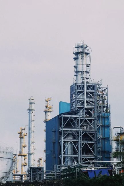
The unit-process sequence below is the defensible 2026 default an engineer can drop into a Dallas RFQ without re-deriving the chemistry. Each line is sized for 85–90% overall plant recovery, which is the recovery band where leading fabs currently operate (per IDE Tech, 2026).
CMP line. Equalization → lamella clarification with sludge recirculation → multi-media filter protecting downstream RO → UF → two-pass RO. The lamella clarifier with sludge recirculation densifies the metal-hydroxide sludge and reduces clarifier footprint, which matters in a Richardson fab with limited pad space. High-recovery RO is set to 85–90% recovery; concentrate is sent to a brine concentrator.
Fluoride line. pH adjustment with lime or CaCl2 to precipitate CaF2 (Ksp ≈ 3.9 × 10⁻¹¹) → lamella clarifier with sludge recirculation → sand/anthracite filter → RO. RO concentrate goes to a brine concentrator or ZLD crystallizer; fluoride breakthrough below 10 mg/L is the typical target before any membrane (per IDE Tech, 2026).
UPW reject / rinse reuse. Two-pass RO with EDI polishing → degasification → UV/H2O2 AOP to break down trace photoresist and solvent residues → return to UPW storage. AOP hydroxyl-radical oxidation is the only practical way to drop TOC below 1 ppb for UPW feed (per IDE Tech, 2026).
Cooling-tower blowdown (data hall). Side-stream filtration (typically 5–10% of loop flow) → PLC-controlled chemical dosing skid for scale and corrosion inhibition → high-recovery industrial RO system for TDS reduction → blended back into the cooling loop. Where PFAS indicators are present, AOP plus GAC polishing is added downstream of RO.
PFAS polishing (whole plant). Granular activated carbon or ion-exchange resin downstream of RO on the combined spent-rinse stream, sized for the 2026 EPA MCLs (4 ng/L PFOA, 4 ng/L PFOS) rather than the older 70 ng/L health-advisory level. This is the step that protects against CERCLA reporting exposure, since PFAS releases above the reportable threshold now trigger Superfund notification (per IDE Tech, 2026).
| Stream | Unit-Process Sequence | Key Design Target | 2026 Best Practice |
|---|---|---|---|
| CMP slurry | EQ → Lamella → MMF → UF → 2-pass RO | Cu/Ni/W < 0.1 mg/L; recovery 85–90% | Sludge recirculation on clarifier |
| Fluoride etchant | Ca precipitation → Lamella → Sand/anthracite → RO | F⁻ < 10 mg/L pre-RO | ZLD on concentrate |
| UPW reject / rinse | 2-pass RO → EDI → Degas → UV/H2O2 AOP | TOC < 1 ppb; resistivity > 18.2 MΩ·cm | Return to UPW storage |
| Cooling-tower blowdown | Side-stream filter → Dosing → RO → blend | Cycles of concentration 6–8; TDS < 500 mg/L blended | AOP + GAC if PFAS present |
| PFAS polishing | GAC or IX resin post-RO | PFOA/PFOS < 4 ng/L (EPA MCL) | Sized for MCL, not health advisory |
Recovery Targets, Water Cost, and the Dallas Reuse Math
State-of-the-art fabs recover 85–90% of their wastewater using high-recovery RO plus thermal polishing; ZLD is reserved for brine that cannot be sent to POTW or surface water (per IDE Tech, 2026). For a Dallas data hall, a 100 MW campus consuming roughly 528,000 gallons per day can offset a meaningful share of Upper Trinity RW demand with even a 30% reuse rate, which is well below the 50–70% reuse operators are now targeting in water-stressed corridors (per market.us, 2026).
The trade-off is not linear. Every additional 5% recovery above 85% typically doubles the unit cost of the next step, because membrane-based recovery runs out of headroom and thermal brine concentration takes over. Frame this as a stepped cost curve when defending the 85–90% target to finance: pushing to 95% is rarely justifiable on water-cost grounds alone, but is sometimes justifiable on CERCLA-risk grounds.
The water-energy nexus now belongs in the EHS scope. AI racks at 40–120 kW drive cooling demand up sharply, and U.S. data-center electricity is projected to reach 325–580 TWh by 2028 (per DOE/LBNL, cited in market.us, 2026). On the Texas grid, more cooling water means more pumping and chiller load, which is why the TCEQ reviewer will ask about both withdrawal volume and reuse rate in the same TPDES application.
| Facility Profile (Dallas, 2026) | Water Use | Realistic Recovery | Endpoint | Cost-Band Note |
|---|---|---|---|---|
| Greenfield 300 mm fab (Richardson) | Up to 10 MGD | 85–90% | UPW reuse + TCEQ-permitted blowdown | Membrane-driven; thermal only for brine |
| 100 MW AI data hall (Alliance/Legacy) | ~528,000 gpd | 50–70% | Cooling-tower loop blend | Side-stream RO dominates capex |
| Hyperscale data-hall campus | 1.5–5 MGD | 50–70% | Cooling loop + occasional reuse offset | Volume discounts on RO membranes |
| Fab + data-hall co-located | Combined, site-specific | 85–90% fab, 50–70% data hall | Shared brine line to ZLD | Best economics for ZLD capex |
TCEQ Permitting, PFAS Documentation, and the 2026 Compliance Stack

A Dallas fab or large data hall sits under a Texas Pollutant Discharge Elimination System (TPDES) multi-sector industrial permit for process wastewater and stormwater, plus an industrial user permit from the receiving POTW (e.g., the City of Dallas Water Utilities or Trinity River Authority) if discharge is to sewer. TCEQ now references WRAP 2.0 Action 3.10 when reviewing cooling-tower reuse proposals, so a project narrative that cites recycled-water end use and PFAS removal to the 2026 MCLs reads well in pre-application meetings (per market.us, 2026).
The federal stack a Dallas EHS lead has to track in 2026 is real and overlapping: EPA PFAS MCLs of 4 ng/L for PFOA and PFOS, CERCLA reporting thresholds for PFAS releases (which is what makes those MCLs operationally significant), RCRA hazardous-waste characterization for CMP and solvent streams, and the new WRAP 2.0 Action 3.10 pathway for recycled-water permits. PFAS releases above the reportable CERCLA threshold now trigger federal cleanup exposure, not just state enforcement, which is why the PFAS polishing step belongs in the base design rather than as a future upgrade.
Centralized waste treaters with a roughly 200-mile Dallas service radius are a legitimate option for surge volumes, glycol offloading, and PFAS-destruction campaigns (per Valicor coverage, 2026), but on-site treatment remains the norm for fab process streams because the chemistry is too site-specific to haul economically. A blended model, on-site RO and precipitation with off-site PFAS destruction and glycol consolidation, is what most Dallas sites end up specifying in their 2026 RFQs.
Frequently Asked Questions
What is the realistic 2026 recovery target for a Dallas fab?
State-of-the-art fabs recover 85–90% of total wastewater using high-recovery RO plus thermal polishing; ZLD is reserved for the brine that cannot be sent to POTW or surface water (per IDE Tech, 2026). Pushing above 90% is rarely justifiable on water-cost grounds alone because each additional 5% recovery typically doubles the unit cost of the next step.
Which wastewater stream should a Dallas data hall size its treatment plant around?
Cooling-tower blowdown dominates the data-hall water balance at 85–95% of total volume, typically 1.5–5 MGD for a major campus (per market.us, 2026). Side-stream filtration plus a high-recovery industrial RO system (high-recovery industrial RO system) sized for 50–70% cooling-water reuse is the 2026 default.
How does a Dallas fab handle PFAS without triggering CERCLA liability?
Treat to the 2026 EPA PFAS MCLs of 4 ng/L for PFOA and PFOS using GAC or ion-exchange resin downstream of RO, sized for the MCL rather than the older 70 ng/L health advisory, and document the destruction step in the TPDES application. Releases above the CERCLA reportable threshold now trigger Superfund notification, which is why the polishing stage belongs in the base design.
Can an MBR system be used on a semiconductor wastewater train?
Yes, but only on specific organic-rich side-streams such as solvent-bearing rinses or photoresist overflows, not on the main CMP or fluoride lines. An MBR system for organic-rich side streams is typically placed upstream of AOP and RO when TOC loading is high enough to foul the membranes, with biological treatment reducing organics before the polishing train.