
Why Sludge Dryers Fail: The Seven Operator Calls
Operators call about seven recurring symptoms that account for the vast majority of sludge dryer tickets: low evaporation rate, wet cake at discharge, caking or scaling on heat surfaces, bearing or gearbox overheating, excessive odor or vapor, foaming in the feed chamber, and conveyor or screw carryover. Each maps to a specific physical failure mode inside the dryer: heat-transfer surface fouling, residence-time starvation, agitator mechanical degradation, vent-system failure, upstream feed chemistry drift, or screw/conveyor geometry wear. A well-conditioned dryer should reduce cake moisture from 88.69–90.84% inlet to 7.78–13.30% outlet under mixing conditions, as documented in the Hue University solar tunnel study (Hue University, 2024); a reading of 14.78–19.52% outlet in the same study signalled partial mixing failure and is a useful proxy for any indirect-heat unit whose agitator is not renewing the film against the heat surface. The troubleshooting discipline for sludge dryers therefore sits downstream of, and is tightly coupled to, the biological step that produced the sludge — a framing consistent with how activated-sludge troubleshooting is treated in the pulp-and-paper literature (BioResources, S1). For most plants, the cheapest diagnostic is the upstream dewatering device, because the plate and frame filter press sets the feed dryness the dryer must handle.
Feed Conditioning: The Variable That Decides Everything
Field data show that 60–70% of "dryer underperformance" tickets are actually dewatering tickets in disguise (HydropureWater field data, 2026). The target dryness into a paddle or thin-film sludge dryer is 18–25% dry solids (DS) from the filter press; below 18% DS the dryer is being asked to evaporate free water, not bound water, and the available heat-transfer area runs out before the cake reaches nameplate exit moisture. Polymer or electrolyte dose drift, sludge age, and hydraulic or organic shock loading all change cake structure. A pulp-and-paper case study documented an upstream system recovering from a 1,575 mg/L COD shock load through biostimulant dosing at 1 ppm for 30 days, returning effluent COD to roughly 80 mg/L and stabilizing the biological step that feeds the dryer (BioResources, 2016, S1). The practical implication for dryer operators: when feed quality drifts, stabilize the upstream biology with an automatic polymer and biostimulant dosing system before adjusting dryer parameters. Foaming at the feed chute usually traces to surfactants, a high SVI, or over-polymerized sludge; a quick 200 mL graduated-cylinder settling test (10 minutes) distinguishes these, and any anti-foam dose belongs on the sludge line, not inside the dryer, to protect heat surfaces. Routine checks upstream of the dryer, including inlet works troubleshooting, also reduce ragging and grit that downstream agitators have to absorb.
Symptom-to-Fix: Low Evaporation Rate and Wet Discharge Cake
Low evaporation rate and wet cake at discharge are the most common throughput-and-quality complaint. The probable causes, in priority order, are heat-surface fouling or scaling, low jacket or thermal-oil temperature, excessive feed rate, low agitator RPM, and steam-trap failure on indirect-heat units. The diagnostic sequence is: (a) check the inlet-to-outlet product temperature differential against the nameplate value — a shrinking delta on stable feed is the earliest warning; (b) inspect heat-surface scale thickness through the inspection port (typically 1–3 mm of calcium or polymerized-oil film is enough to cut evaporation by 20–30%); (c) verify thermal-oil or steam supply pressure is at the dryer's design value, usually 4–10 bar(g) for steam-heated units; (d) measure agitator current draw against nameplate full-load amps — a 15–20% drop typically indicates worn or broken paddles that are not renewing the film. Corrective actions are to descale with a manufacturer-approved CIP cycle, restore or replace the steam trap, re-rate feed to the design kg water/m²·h, and replace worn agitator blades. The target outcome is exit moisture under 15% in continuous units — compare to the 7.78–13.30% benchmark from the solar tunnel work (Hue University, 2024) — and a product temperature held within the dryer's nameplate band. Pairing this work with the steps in the sludge thickener maintenance guide keeps the upstream envelope stable.
Symptom-to-Fix: Caking, Scaling, and Heat-Surface Fouling
Caking and scaling are the single most damaging fault for indirect-heat dryers, because an insulating layer on the heat surface starves the entire unit of evaporation capacity. The cause chain is usually high-calcium or high-silica feed water depositing inorganic scale, oil or grease carryover from a DAF pre-thickener forming a polymerized film, or over-dried cake burning onto the surface when residence time runs too long. A surface thermocouple reading 5–10°C below the design bulk temperature is the diagnostic confirmation; the same effect was visible in the Hue University study, where the no-mixing runs landed at 14.78–19.52% outlet moisture, effectively a fouled-heat-surface proxy for any dryer type. Corrective action is a scheduled CIP with a manufacturer-approved acid/alkaline rotation (typically 2–4% caustic followed by 1–3% inhibited acid), mechanical scraper re-tensioning to the supplier's torque spec, and a review of the upstream high-efficiency sedimentation tank or DAF for oil/grease breakthrough. Prevention is an online conductivity or pH probe on the feed line that alarms when TDS spikes beyond the dryer's design limit, which for most indirect-heat units sits in the 5,000–15,000 mg/L range.
Symptom-to-Fix: Bearing Overheating, Gearbox Trips, and Mechanical Wear
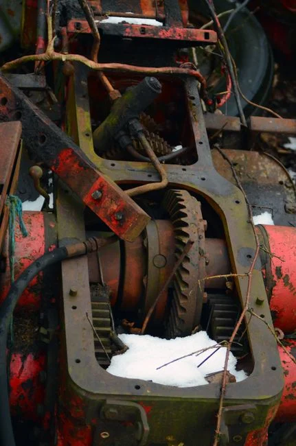
Mechanical wear is the most expensive failure mode in paddle and thin-film dryers, both in parts and in lost production. The cause chain is usually misalignment from foundation settling, worn seals letting sludge ingress into bearings, under-lubrication, or over-torque from caked material in the paddle zone. Trending bearing-housing temperature is the first diagnostic — a 10°C rise above the unit's clean baseline is the standard warning band, and 15°C typically forces a controlled shutdown (per ISO 17359 condition-monitoring practice). Vibration velocity should be checked against the ISO 10816 thresholds for the agitator's RPM class; a doubling of RMS velocity month-over-month is the classic precursor to a bearing failure. Corrective steps are to re-align the shaft to within 0.05 mm, re-pack or replace seals, restore the grease schedule to manufacturer intervals, and clear the paddle zone by stopping feed and running the agitator at slow speed (typically 30–50% of nameplate RPM) with heat applied. Predictive maintenance practice is to install wireless vibration sensors on each agitator bearing and trend monthly, replacing bearings on condition rather than on a calendar — an approach the sludge thickener maintenance guide applies to the same agitator-class equipment.
Symptom-to-Fix: Odor, Vapor, and Off-Gas Complaints
Odor is the fault that forces shutdowns even when the dryer is mechanically healthy, because it draws regulatory and community attention. The cause chain is almost always anaerobic pockets in the feed (septic sludge), low dryer temperature leaving vapor undeodorized, a failed condenser on a closed-loop dryer, or inadequate vent scrubbing. The diagnostic is to measure H₂S at the dryer vent with a portable detector — anything above 5 ppm at the vent stack is a complaint risk — and to pull a feed sample for ORP. Septic sludge reads negative ORP, typically -100 to -300 mV, and is the single most common cause. Corrective action is to route the feed through a fresh holding tank with mild aeration (target ORP above +50 mV), restore condenser water flow to design, and verify the vent scrubber pH is in the 9–10 band for H₂S capture using a properly sized gas scrubber. When odor persists despite these steps, evaluate switching to a thin-film or paddle dryer with an integrated deodorization chamber — the solar-tunnel data at 55±5°C (Hue University, 2024) confirm that low-temperature units do not thermally destroy H₂S.
Sludge Dryer Parameter Targets: The Quick-Reference Table
Print the table below and pin it next to the MCC. The "design intent" column is anchored to the Hue University solar-tunnel benchmark (88.69–90.84% inlet, 7.78–13.30% outlet under mixing, 55±5°C tunnel temperature) and to standard operating ranges for the other parameters. The "trouble threshold" column flags the boundary at which the operator should escalate, and the "first action" column maps each breach back to the seven operator calls defined earlier.
| Parameter | Design intent | Trouble threshold | First action |
|---|---|---|---|
| Feed cake dryness (DS) | 18–25% | < 18% DS | Check filter press, polymer dose |
| Dryer surface / tunnel temperature | 55 ± 5 °C (solar) / per nameplate (indirect) | > 5 °C below setpoint | Inspect heat-surface scale |
| Exhaust temperature | Within 10 °C of inlet product temperature | > 15 °C rise on stable feed | Check steam trap, thermal-oil supply |
| Agitator RPM | Per nameplate (typically 5–30 rpm) | > 15% drop from setpoint | Inspect paddles, drive current |
| Residence time | Per nameplate (typically 1–4 h continuous) | Reduced by feed-rate creep | Re-rate feed to design kg water/m²·h |
| Exit cake moisture | 7.78–13.30% (solar, with mixing) | 14.78–19.52% (no-mixing proxy) | Restore agitator film renewal |
| Energy use | Per nameplate (typically 800–1,200 kcal/kg water) | > 20% rise on stable feed | Descale heat surfaces |
| Vent H₂S (closed loop) | < 2 ppm at stack | > 5 ppm at stack | Check feed ORP, scrubber pH |
| Bearing housing temperature | Baseline ± 5 °C | +10 °C above baseline | Inspect lubrication, alignment |
Preventive Maintenance: A 30-90-180 Day Cadence
Converting troubleshooting into a recurring program is what lifts a plant from firefighting to predictable uptime. The 30-day checks are the fast loop: bearing temperature log, agitator current log, vent scrubber pH, and exhaust temperature trend — all of which can be pulled from the DCS without opening the unit. The 90-day checks add physical inspection: agitator seal condition, heat-surface scale thickness via the inspection port, and CIP chemical strength titration to confirm the cleaning cycle is still cutting fouling. The 180-day checks are the full opening: paddle and scraper blade wear measurement against the supplier's wear-limit gauge, gearbox oil analysis for particle count and water contamination, and thermal-oil or steam-trap refurbishment. The cadence is intentionally tied to the upstream sludge thickener maintenance guide so the dryer and the dewatering device stay in the same operating envelope, which is the only reliable way to keep exit moisture inside the 7.78–13.30% benchmark under mixing conditions.
Frequently Asked Questions
What is the target exit moisture for a sludge dryer?
A well-conditioned paddle or thin-film sludge dryer should deliver cake at 7.78–13.30% moisture under mixing conditions, starting from 88.69–90.84% inlet moisture as documented in the Hue University solar-tunnel study (Hue University, 2024). Readings in the 14.78–19.52% range signal partial mixing or heat-surface fouling and should trigger agitator and scale inspection.
Why is my dewatered cake too wet for the dryer?
The most common cause is upstream dewatering underperformance at the filter press. The target feed into a paddle or thin-film dryer is 18–25% dry solids (DS); below 18% DS the dryer is being asked to evaporate free water and runs out of heat-transfer area. Verify polymer dose, belt/press cloth condition, and sludge age, and consider a plate and frame filter press capable of consistent 22–25% DS output.
How do shock loads upstream affect dryer performance?
Hydraulic and organic shock loads destabilize the activated-sludge step that feeds the dryer. A documented pulp-and-paper case study showed a 1,575 mg/L COD shock load recovered to roughly 80 mg/L effluent COD after 30 days of biostimulant dosing at 1 ppm (BioResources, 2016, S1). For the dryer operator, the practical lever is an automatic polymer and biostimulant dosing system that holds the upstream biology in a stable envelope so feed cake structure does not drift day to day.
What is the fastest field test for caking on heat surfaces?
Compare the surface thermocouple reading to the design bulk temperature at steady feed. A 5–10 °C shortfall on stable feed is the classic fouled-surface signal. Confirm by opening the inspection port and measuring scale thickness; 1–3 mm of calcium or polymerized-oil film is enough to cut evaporation by 20–30% and is removable with a manufacturer-approved acid/alkaline CIP rotation.
What temperature destroys H₂S in a sludge dryer?
Low-temperature solar or tunnel units operating at 55 ± 5 °C do not thermally destroy H₂S (Hue University, 2024). The reliable control is chemical: hold feed ORP above +50 mV through mild aeration in a holding tank, and maintain vent scrubber pH in the 9–10 band. A sealed paddle or thin-film dryer with an integrated deodorization chamber is the appropriate unit class when odor control is a permit condition.