Why a Bayer-Class Plant Cannot Run on Activated Sludge Alone After Expansion
A Bayer-class chemical and pharmaceutical plant that grows flow and load by 30–60% cannot meet its discharge envelope on a single activated-sludge step, because conventional biology clears bulk BOD, COD, and ammonia but leaves trace APIs, AOX, and antibiotic-resistance genes largely untouched. The AMBIO review by Rogowska et al. (2019) documents that pharmaceuticals and personal-care products are only partially removed in standard WWTPs, with treated effluents characterized almost exclusively by BOD, COD, and TSS while trace organics pass through unregulated. The Frontiers in Microbiology (2012) Lausanne dataset quantified the gap further: only 0.5–1 log reduction in multiresistant bacteria across a full-scale activated-sludge plant, and 9 of 11 antibiotics showed higher or equal resistance in treated effluent than in raw sewage — direct evidence that biology alone is necessary but not sufficient for a pharma effluent. The expansion trigger matters because a 30–60% jump in flow and load without AOX polishing pushes the post-biology AOX band of 1–5 mg/L toward 3–10 mg/L in the final effluent, breaching the 1 mg/L EU surface-water cap. Typical Bayer-class influent sits at COD 1,000–10,000 mg/L for pharma, sometimes >10,000 mg/L in API mother-liquor streams, with the Harremoes (1992) partition for the mixed stream splitting roughly 200 g/m³ suspended, 65 g/m³ colloidal, and 85 g/m³ soluble out of about 350 g/m³ total. The downstream sections below show how a multi-barrier train converts those influent bands into a discharge envelope of COD <50 mg/L, AOX <1 mg/L, and TN ≤40 mg/L.
Source Segregation and Equalization: The Two Decisions That Decide Everything Downstream
Source segregation is the highest-leverage front-end decision on a Bayer-class site: high-strength solvent and API mother-liquor streams route to dedicated stripping, recovery, or thermal destruction rather than diluting into the mixed influent, because letting a 50,000 mg/L solvent stream into a 5,000 mg/L mixed stream strips nitrifier activity and risks deflagration in covered aeration tanks. Equalization follows, sized at 6–24 h hydraulic retention time and pushed to 12–24 h on batch API plants whose flow and load swing 2–4× across a shift; equalization must be sized from peak-shift flow, not from average flow, or the chemistry downstream will oscillate. Chemical precipitation runs next, with FeCl3 or polyaluminum chloride dosed at 50–150 mg/L and pH held at 7–8 to drop colloidal COD and co-precipitate heavy metals before biology. Nitrifiers lose activity below pH 6.5 and above pH 9.0, so pH is held inside the 6.5–8.5 band — a tighter window than most permits require, because biology is more sensitive to pH than the consent envelope. Neutralization stoichiometry is for design only: 0.98 mg/L H2SO4 or 0.72 mg/L HCl per mg/L alkalinity, or 0.8 mg/L NaOH per mg/L acidity, with the final dose set by jar test and online pH feedback rather than the stoichiometric number. On a 24/7 pharma shift, the only way those two decisions stay reliable is PLC-controlled coagulant and pH injection through an automatic chemical dosing system tied to online pH and ORP probes — grab-sample control will not hold a 30–60% post-expansion load inside the design window.
MLE Biological Nutrient Removal: The Load-Removal Workhorse
The activated-sludge configuration that handles a Bayer-class post-expansion load is a modified Ludzack-Ettinger (MLE) loop, with an aerobic zone for nitrification (NH4+ → NO3−), a pre-anoxic zone for denitrification (NO3− → N2), and an internal mixed-liquor recycle at 2–4× the influent flow to push nitrate back into the anoxic zone. Operating windows matter more than the configuration name: F/M at 0.05–0.3 kg BOD/kg MLSS·d, SRT at 5–15 d, and aeration DO at 2–4 mg/L — values outside those windows cause nitrifier washout, denitrification failure, or bulking sludge. Methanol or acetic acid dosing is standard once chemical precipitation strips the easy carbon, because the residual carbon after FeCl3 dosing is mostly soluble and the denitrifiers need an external electron donor to reach TN 20–40 mg/L. Post-biology design targets on a Bayer-class plant land at COD 150–250 mg/L, NH4-N <5 mg/L, TN 20–40 mg/L, and AOX still 1–5 mg/L — enough to meet conventional bulk-parameter consents but not enough to clear trace APIs and ARG load. The expansion sizing question is the one most engineers get wrong: a 30–60% load rise usually pushes a single MLE train past its DO and recycle limits, so the design choice is a parallel biological train sized to match the new flow, or an IFAS/MBBR hybrid that adds biofilm surface area to the existing basin rather than oversizing one reactor — the trade-offs are laid out in the AAO/MLE biological train design reference and the IFAS process flow diagram engineering guide.
Advanced Oxidation with Ozone or Ozone/H2O2: Where Trace APIs and AOX Actually Disappear
Advanced oxidation is the unit operation that closes the trace-API and AOX gap that biology leaves open. The operating window is 5–15 mg O3 per mg DOC, with H2O2 added at a 0.3–0.5 molar ratio to O3 to drive hydroxyl-radical formation against ozone-refractory APIs that direct ozonation only partially oxidizes. Reported removal exceeds 90% for many trace pharmaceuticals when AOP follows biological treatment, which is the number an engineer cites in a permit pre-application. Dose selection is driven by SUVA at 254 nm via an online UV meter, not by grab-sample COD, because DOC and UV absorbance are the load indicators that AOP actually responds to and total COD hides the refractory fraction. Hydrogen-peroxide addition protects against bromide and limits bromate formation, a regulated parameter in EU surface-water discharge with a 10 µg/L limit at drinking-water abstractions. The most cite-ready number for a pharma permit defense is the ARG log-reduction: the AOP+UV combination delivers 1–3 additional log reductions in antibiotic-resistance genes over biology alone (Frontiers in Microbiology, 2012), which is what shifts the permit conversation from "bulk parameters compliant" to "antimicrobial-resistance risk addressed."
MBR Polishing and the Sidestream RO Reuse Loop
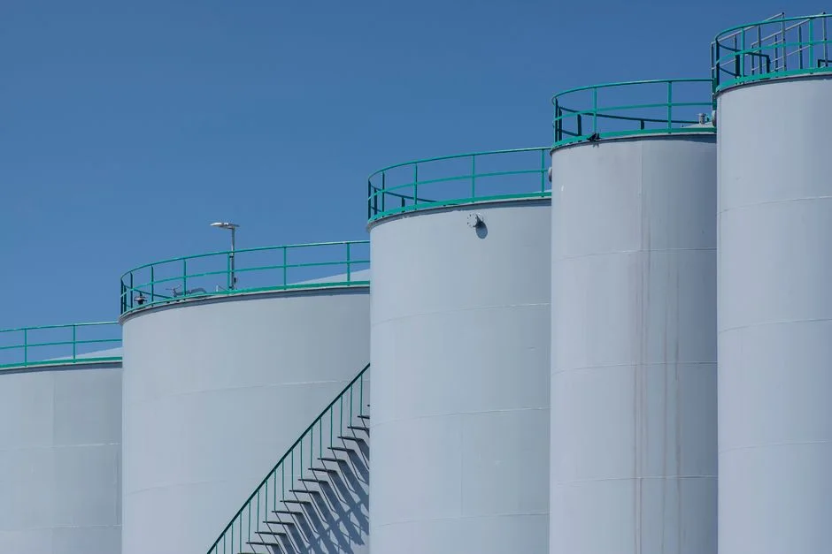
MBR polishing is the bridge between AOP effluent and either discharge consent or a reuse loop. The hardware is a submerged PVDF flat-sheet module at 0.1–0.4 µm pore size, operating at flux 10–25 L/m²·h and TMP 0.1–0.4 bar; flat-sheet is preferred over hollow-fiber in this duty because it tolerates the higher residual COD that an AOP-fed stream carries and back-flushes cleanly with the standard CIP chemicals already on site. Post-MBR targets are COD <50 mg/L, TSS <5 mg/L, AOX <1 mg/L, and an SDI low enough to feed RO without accelerated fouling. A GAC polish (EBCT 10–30 min, periodic thermal reactivation) sits ahead of discharge as a guard that smooths AOP transients during a generator trip or a feed-COD excursion. The reuse side runs as a sidestream RO loop on MBR permeate at 70–85% recovery in a 2:1 or 3:1 array, with CIP intervals held above 30 days once the MBR is operating inside its design window; permeate goes to cooling-tower makeup, boiler feedwater (after a mixed-bed polisher), or process rinse water. The bottleneck is brine management: concentrate at 5–8% TDS has to go to evaporation or to a mechanical vapor recompression (MVR) crystallizer if zero liquid discharge is the site target. The two hardware pieces the engineer specs on the tender are submerged PVDF flat-sheet MBR modules for the polishing step and a multi-stage industrial RO system for the reuse loop. Expansion scaling note: an MBR skid adds capacity in 80–225 m² modules, so a 30–60% load rise is usually met by adding one or two cassettes to the existing frame rather than replacing the train.
| Unit Operation | Design Parameter | Operating Window | Function |
|---|---|---|---|
| Equalization | HRT | 12–24 h (batch API) | Flatten flow and load swings of 2–4× |
| FeCl3 precipitation | Dose / pH | 50–150 mg/L, pH 7–8 | Drop colloidal COD, co-precipitate metals |
| MLE biology | MLR / F:M / SRT / DO | 2–4× Q / 0.05–0.3 / 5–15 d / 2–4 mg/L | COD and TN removal |
| Methanol/AcOH dosing | Dose basis | 3 mg MeOH per mg NO3-N | External carbon for denitrification |
| Ozone/H2O2 AOP | O3:DOC / H2O2:O3 | 5–15 / 0.3–0.5 | Trace API and AOX destruction |
| Submerged PVDF MBR | Flux / TMP / Pore | 10–25 L/m²·h / 0.1–0.4 bar / 0.1–0.4 µm | Solids barrier, RO feed prep |
| GAC polish | EBCT | 10–30 min | AOP transient guard |
| Multi-stage RO | Recovery / Array | 70–85% / 2:1 or 3:1 | Reuse permeate |
| MVR crystallizer (ZLD) | Brine feed TDS | 5–8% TDS | Zero liquid discharge |
Design Targets and Discharge Envelope for a Bayer-Class Site
The discharge envelope a Bayer-class site works inside in the EU and Germany is COD ≤250 mg/L, BOD <30 mg/L, AOX ≤1 mg/L, and TN ≤40 mg/L for direct surface-water discharge, with stricter limits at receiving waters that feed drinking-water abstractions. The post-biology band is COD 150–250 mg/L, NH4-N <5 mg/L, TN 20–40 mg/L, AOX 1–5 mg/L; post-MBR tightens to COD <50 mg/L, TSS <5 mg/L, AOX <1 mg/L, and >90% trace API removal across the AOP+MBR combination. Chlorine residual for surface-water discharge is 0.5–1.0 mg/L, but on-site ClO2 generation is preferred over chlorine at pharma sites because ClO2 does not form AOX byproducts when it contacts AOP effluent, and any AOX formation works against the 1 mg/L cap. The binding constraint is AOX, not COD, and that constraint is what justifies the AOP and GAC stages on the train. For sites that need a residual disinfectant before surface-water discharge, an on-site chlorine dioxide generator is the standard fit because it holds the 0.5–1.0 mg/L residual without driving the AOX number back up.
| Parameter | Raw Influent | Post-Biology | Post-MBR | Discharge Limit (EU/DE) |
|---|---|---|---|---|
| COD (mg/L) | 1,000–10,000 | 150–250 | <50 | ≤250 |
| BOD (mg/L) | 500–5,000 | <30 | <10 | <30 |
| NH4-N (mg/L) | 50–300 | <5 | <1 | <10 |
| TN (mg/L) | 80–500 | 20–40 | <20 | ≤40 |
| AOX (mg/L) | 5–30 | 1–5 | <1 | ≤1 |
| TSS (mg/L) | 200–1,000 | 30–80 | <5 | <30 |
| Trace APIs | Variable | Partially removed | >90% removed | Site-specific ERA |
| ARG log reduction vs. raw | — | 0.5–1 log | 1–3 log (with AOP+UV) | — |
| Residual disinfectant (mg/L) | — | — | 0.5–1.0 (ClO2) | 0.5–1.0 |
When to Step Up from a Parallel Biological Train to RO and ZLD

The CAPEX decision on a Bayer-class expansion comes down to three triggers: discharge consent, freshwater demand, and brine disposal cost. If the consent is the EU surface-water cap and freshwater is cheap, a parallel MLE train plus AOP and MBR is the lowest-CAPEX path that clears the envelope, and RO is optional. If freshwater is scarce or the site already runs cooling towers at high cycles of concentration, a sidestream RO loop at 70–85% recovery pays back through displaced freshwater, typically inside 3–5 years at German industrial water tariffs. The step up to ZLD via MVR crystallizer is triggered by brine disposal cost rather than by consent: once the 5–8% TDS RO concentrate exceeds what the local wastewater utility will accept, or once the site targets zero liquid discharge for water-stewardship reporting, the MVR crystallizer is the unit operation that closes the mass balance, with energy demand around 25–35 kWh per m³ of distillate for a feed at 5–8% TDS. The decision rule: add a parallel biological train when biology is the bottleneck, add RO when reuse economics justify it, and add MVR only when brine disposal is the binding constraint.
Frequently Asked Questions
What ETP train does a Bayer-class chemical and pharma plant need after a 30–60% capacity expansion?
A multi-barrier train in this order: source segregation of solvent and API mother-liquors, 12–24 h equalization, FeCl3 precipitation at pH 7–8, MLE nitrification/denitrification at 2–4× internal recycle and F/M 0.05–0.3, ozone/H2O2 AOP at 5–15 mg O3/mg DOC, submerged PVDF MBR at 10–25 L/m²·h, and a sidestream RO loop at 70–85% recovery. Post-biology targets COD 150–250 mg/L, TN 20–40 mg/L, AOX 1–5 mg/L; post-MBR targets COD <50 mg/L, AOX <1 mg/L, >90% trace API removal.
Why is a single activated-sludge step not enough for a Bayer-class site?
Conventional biology removes bulk BOD, COD, and ammonia but only 20–60% of most trace APIs and 0.5–1 log of multiresistant bacteria (Frontiers in Microbiology, 2012). The AMBIO review (Rogowska et al., 2019) confirms that pharmaceuticals and personal-care products pass through standard WWTPs unregulated, which is why AOP, MBR, and RO polishing are added downstream.
When should a Bayer-class expansion add RO, and when should it step up to ZLD via MVR?
Add a sidestream RO loop when cooling-tower makeup or boiler feedwater demand justifies 70–85% permeate recovery — typical payback is 3–5 years at German industrial water tariffs. Step up to ZLD via MVR crystallizer when RO concentrate at 5–8% TDS exceeds what the local utility will accept, or when the site targets zero liquid discharge; MVR energy demand is roughly 25–35 kWh per m³ of distillate at that feed strength.
How does the Bayer-class design compare to ETP sizing for an FMCG factory or brewery expansion?
The Bayer-class train carries AOP and RO because trace APIs and AOX are the binding constraints, while an FMCG factory expansion runs a biological train plus MBR and skips AOP unless surfactants drive a COD consent problem, and a brewery expansion runs MLE plus a smaller RO loop because effluent is lower-strength and free of halogenated organics. For a sector comparison, see the ETP sizing for FMCG factory expansion guide and the Heineken brewery expansion ETP guide; for a regional pharma reference, see the pharma wastewater treatment in Bahrain guide. The Danone dairy plant expansion sits in between, with biological nutrient removal and RO but no AOP, as detailed in the Danone dairy plant expansion ETP guide.