
What an Automotive Assembly Plant ETP Actually Has to Treat
An automotive assembly plant generates seven distinct wastewater streams, and an Effluent Treatment Plant (ETP) sized for post-expansion operation must be characterized against every one of them before a single piece of equipment is selected. Those streams are: cathodic electrodeposition (CED) rinse water, phosphate and nickel pre-treatment rinses, paint shop overspray and booth scrubber water, metalworking fluid emulsions, stamping lubricants, cooling tower blowdown, and domestic sewage from the workforce. Mixing them into a common header without characterization is the single most common cause of biological-stage upsets in GM-style facilities, because the COD, metals, and oil profiles of each stream are an order of magnitude apart.
The compliance anchor for the U.S. assembly sector is 40 CFR 433 Metal Finishing, which sets categorical pretreatment limits for any plant discharging to a POTW. Daily maximum values are 2.07 mg/L zinc, 1.71 mg/L total chromium, 0.43 mg/L nickel, 1.48 mg/L lead, and 0.60 mg/L cadmium, with monthly averages running roughly 30–50% lower (per EPA 40 CFR 433). Local POTW limits typically layer on top of the federal categorical standards — Detroit Water and Sewerage Department (DWSD), for example, applies additional conventional pollutant caps on oil and grease, total suspended solids, and pH range (6.0–10.0 S.U.).
Influent variability is the operational reality that dictates equalization volume. Flow can swing 2–3x between single-shift and double-shift operation, and paint-shop dump cycles can deliver a slug of overspray solids in 20 minutes that would otherwise starve a biological stage for the rest of the day. Per WTE Infra's ETP guide, equalization is the most important practical component because biological and chemical systems perform more reliably when sudden flow and concentration swings are buffered — and the same source is explicit that there is no universal ETP design suitable for every industry. The treatment train has to be developed around the wastewater characteristics, not copied from another sector.
| Stream | Typical Pollutants | Typical Concentration Range | Treatment Target |
|---|---|---|---|
| CED rinse water | Zinc, lead, phosphate, surfactants | Zn 5–30 mg/L, Pb 1–10 mg/L | 40 CFR 433 limits |
| Phosphate/Ni pre-treatment | Nickel, zinc, phosphate, fluoride | Ni 2–20 mg/L, PO₄ 20–200 mg/L | 40 CFR 433 Ni limit (0.43 mg/L daily max) |
| Paint overspray / booth scrubber | Resin solids, pigments, solvents, COD | COD 1,000–6,000 mg/L, TSS 500–3,000 mg/L | DAF removal, then biological |
| Metalworking fluid emulsion | Emulsified oil, surfactants, COD | Oil 200–5,000 mg/L, COD 5,000–30,000 mg/L | DAF + chemical break |
| Stamping lubricant | Free oil, tramp grease, TSS | Oil 500–10,000 mg/L | DAF, oil-water separator |
| Cooling tower blowdown | High TDS, chromate inhibitors, biocides | TDS 1,000–5,000 mg/L | RO or side-stream softening |
| Sanitary sewage | BOD, TSS, ammonia, pathogens | BOD 200–400 mg/L | Biological, disinfection |
How Plant Expansion Changes the ETP Design Basis
Expansion is not a single number — it is two different load vectors, and an ETP can be hydraulically fine while being organically overloaded. A 50% capacity increase that adds a new paint line typically delivers 30–50% additional hydraulic flow but can double the COD load from overspray, because paint residues are the most concentrated stream in the plant. A new stamping cell, by contrast, primarily adds oil and grease mass with modest flow change, which forces a re-rating of the DAF hydraulic and solids-loading capacity rather than the biological stage.
The most common expansion mistake is treating the new flow as a uniform 20–80% step and scaling every unit equally. In practice, a new body shop increases oil/grease load and may require a DAF upsizing; a new paint shop may push the existing biological stage past its F/M (food-to-microorganism) ratio envelope, requiring MBBR media addition or an MBR membrane retrofit rather than just a larger aeration tank. Equalization must be sized to buffer the new peak-to-average flow ratio, which per WTE Infra's ETP guide typically requires 8–24 hours of retention for biological systems to absorb diurnal swings without losing nitrification or suffering sludge washout (per WTE Infra, 2025).
Quantitatively, a 30% capacity increase at a 1,000 m³/d plant adds roughly 300 m³/d of flow but may add 600–800 kg/d of additional COD load if the new line is paint-dominated. The ETP design basis must be rebuilt from the new stream-by-stream characterization, not extrapolated from the old influent data — which is the specific gap that most generic ETP primers (including the WTE Infra overview) leave for the project engineer to fill.
The Treatment Train a Post-Expansion ETP Needs
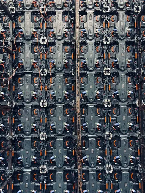
A correctly sequenced ETP for an expanded assembly plant runs in seven stages, each sized from the post-expansion influent profile. A rotary bar screen for headworks protection is the first unit operation — typically 5–10 mm aperture — to keep rags, plastics, and large solids out of downstream equipment. From there, an equalization basin (8–24 h retention) dampens the flow and concentration swings that single-shift/double-shift transitions and paint-shop dumps otherwise impose on the downstream train.
The third stage is a DAF unit for oil and paint overspray removal, sized at hydraulic loading rates of 20–40 m/h on the lamella zone and air-to-solids ratios of 0.02–0.05 kg air/kg TSS. The DAF handles free and emulsified oils, paint overspray solids, and floating FOG in a single step, typically achieving 80–95% oil and TSS removal before any chemistry is applied. Stage four is chemical precipitation and pH adjustment using a PLC-controlled chemical dosing for metal precipitation — lime or caustic for pH, with sulfide or DTCR (dithiocarbamate) to precipitate zinc, nickel, chromium, and lead down to the 40 CFR 433 daily maxima.
Stage five is biological treatment, and for an expansion case the most defensible choice is a MBR system for the biological stage, which delivers near-reuse-quality effluent and tolerates the higher MLSS that an overloaded aeration tank would otherwise reject. Stage six is tertiary polishing — multi-media filtration followed by a RO polishing for cooling-tower reuse, with RO recovery typically 70–95% depending on feed TDS. Stage seven is sludge handling using a filter press for metal hydroxide sludge, producing 25–35% dry solids cake for off-site hazardous-waste disposal.
| Stage | Equipment | Design Parameter | Typical Range |
|---|---|---|---|
| 1. Screening | Rotary bar screen | Aperture | 5–10 mm |
| 2. Equalization | Buffer tank with aeration | HRT | 8–24 h |
| 3. DAF | Dissolved air flotation | Surface loading | 20–40 m/h |
| 4. Precipitation | Chemical dosing + clarifier | pH set-point | 8.5–9.5 for Ni, Zn |
| 5. Biological | MBR / MBBR / SBR | MLSS / HRT | MBR 8,000–12,000 mg/L |
| 6. Polishing | MMF + UF + RO | RO recovery | 70–95% |
| 7. Sludge | Plate-and-frame press | Cake DS | 25–35% |
Choosing the Right Biological Stage: MBBR vs MBR vs SBR
The biological stage is where most expansion projects are won or lost, and the choice between MBBR, MBR, and SBR is driven by three site-specific constraints: available footprint, load variability, and the reuse quality of the target effluent. MBBR (moving bed biofilm reactor) handles high organic loading and severe shock loads with no sludge recycle, which makes it robust against paint-shop dump cycles but produces effluent around 30 mg/L TSS and 30–50 mg/L BOD — adequate for POTW discharge but not for direct reuse. MBR (membrane bioreactor) accepts the same loading while delivering 60% smaller footprint than a conventional activated-sludge tank of equivalent capacity, MLSS tolerance up to 12,000–15,000 mg/L, and effluent with under 1 μm suspended solids — the only one of the three that can feed an RO polishing train without an intermediate clarifier (HydropureWater field data, 2026).
SBR (sequencing batch reactor) is a batch system that offers flexibility for low-flow or intermittent operation but consumes 15–25% more aeration energy per kg COD removed than MBBR or MBR because the fill/react/decant cycle runs blowers less efficiently. The decision rule for an expanded automotive ETP: choose MBR when footprint is constrained or reuse to the cooling tower or paint rinse loops is a project requirement, choose MBBR when load swings are severe and reuse is not in scope, and choose SBR only when the influent is genuinely low-flow and intermittent. A modular MBR module can also be retrofitted into an existing aeration basin during a planned shutdown, which is often the lowest-capex path for a 20–40% capacity increase.
| Criterion | MBBR | MBR | SBR |
|---|---|---|---|
| Footprint | Medium | ~60% smaller than CAS | Medium-large |
| MLSS tolerance | 3,000–5,000 mg/L | 8,000–15,000 mg/L | 2,000–5,000 mg/L |
| Effluent TSS | 20–50 mg/L | <1 mg/L | 10–30 mg/L |
| Reuse-ready | No (needs MMF) | Yes (feeds RO) | No (needs MMF) |
| Shock-load tolerance | High | Moderate | Low–moderate |
| Best fit | High swings, no reuse | Constrained site, reuse | Low-flow, intermittent |
Cost Drivers and 2026 Compliance Checklist for the Expanded ETP
There is no single defensible price for a 1 KLD industrial ETP, and the WTE Infra guide is explicit that cost varies with project-specific inclusions. The cost drivers that move a budget by an order of magnitude are: whether the system requires only physico-chemical treatment, or also biological, filtration, automation, membranes, civil works, and sludge dewatering (per WTE Infra, 2025). A DAF-only paint-shop pretreatment system at 500 m³/d will price in a different range from a full biological-plus-RO reuse system at the same flow, and a 20–80% expansion should be evaluated as a fully-loaded scope rather than a scaled extrapolation of the original.
The 2026 compliance checklist for a U.S. assembly plant expansion is: (1) NPDES pretreatment program modification for the new hydraulic and pollutant load, (2) 40 CFR 433 self-monitoring against the categorical daily maxima, (3) local POTW discharge permit revision (e.g., DWSD for any Detroit-area facility), (4) EPA Multi-Sector General Permit (MSGP) coverage for stormwater from the expanded footprint, and (5) state-level review — Michigan EGLE has issued automotive-sector effluent guidance that can layer additional metals or PFAS monitoring requirements onto the federal baseline. A Zero Liquid Discharge engineering guide is worth consulting only when site water-stress or POTW capacity makes full reuse economically justified — typically above 70% reuse, which few assembly plants reach without a major process change. Broader context on reuse technology direction is captured in the 2026 water reuse technology trends review, and pretreatment compliance specifics are covered in the transportation equipment pretreatment compliance guide.
Frequently Asked Questions
What is the typical ETP capacity for a GM-style assembly plant after expansion?
A GM-style assembly plant ETP for a 20–80% expansion typically sits in the 500–3,000 m³/d hydraulic range, with equalization sized for 8–24 hours of retention per WTE Infra's ETP guide (2025). The exact capacity is driven by the post-expansion stream-by-stream characterization, not by the prior flow plus a uniform percentage.
Which biological treatment — MBBR, MBR, or SBR — is best for an expanded automotive ETP?
MBR is the preferred choice when footprint is constrained or treated water is reused to the cooling tower, because MBR effluent is under 1 μm TSS and feeds an RO train directly. MBBR is more robust against severe load swings, and SBR is justified only for genuinely low-flow or intermittent influent — see HydropureWater field data (2026) for the full decision matrix.
What are the 40 CFR 433 Metal Finishing effluent limits for an automotive assembly plant?
The 40 CFR 433 daily maximum categorical limits are 2.07 mg/L zinc, 1.71 mg/L total chromium, 0.43 mg/L nickel, 1.48 mg/L lead, and 0.60 mg/L cadmium, with monthly averages running roughly 30–50% lower (per EPA 40 CFR 433). Local POTW limits layer on top of the federal categorical standards for oil and grease, TSS, and pH.
Does an expanded automotive assembly plant need a Zero Liquid Discharge (ZLD) system?
ZLD is justified only when site water-stress or POTW capacity constraints make full reuse economically defensible — typically above 70% reuse. Most GM-style assembly plants target 30–50% reuse through an RO polishing train on the MBR effluent, which is covered in the Zero Liquid Discharge engineering guide rather than mandated for every expansion.